


43
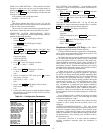
23. The control forces CMP2 (compressor 2) on then waits
5 seconds.
If CSMUX is not in range, the red LED will go on and the
test will stop.
If CSMUX is in range, the red LED blinks once and the
test continues.
24. The control forces CMP2 off.
25. The control forces CMP3 (compressor 3) on, if config-
ured, then waits 5 seconds.
If CSMUX is not in range, the red LED will go on and the
test will stop.
If CSMUX is in range, the red LED blinks once and the
test continues.
26. The control forces CMP3 off.
27. The control forces CMP4 (compressor 4) on, if config-
ured, then waits 5 seconds.
The LID display shows:
Factory/Field Test
Stop
Both the yellow and red LEDs will go off.
28. The control forces CMP4 off.
29. The run test is complete.
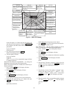
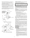
CHECK VFD — The VFD is factory wired and programmed
for proper operation with the unit controls; no installation or
service adjustments are normally required. At unit start-up, the
VFD’s LED will display “0.0 Hz.” Refer to Fig. 33.
POWER UP LID DISPLAY — After completing the auto-
matic run test, perform the following procedures to change the
controller password, set the controller clock, configure sched-
ules, set parameters, view settings, and view alarm history.
1. Set the Remote/Local/Off switch on the front of the unit
to the OFF position. This prevents operation of the fan
and compressors while still providing power to the unit
controls.
NOTE: When the switch is in the OFF position, the red
alarm LED will be lit; this is normal.
2. If the unit access panel (for power and controls) is still on
the unit, remove it in order to view the control modules
during start-up.
3. Switch the main unit power disconnect to ON.
When power is applied to the Omnizone™ system control
panel, the red LED on the top front of the processor module
will flash at a rapid pace (about twice a second) for the first
30 to 60 seconds. This rapid flash will then be replaced by a
slower pace of about once per second.
The green LED below the red LED will start flashing. The
green LED indicates input/output communications for accesso-
ry input output modules and the LID display.
The yellow LED will flash when the controller is broadcast-
ing CCN messages to a laptop or other computer.
The third LED from the bottom of the controller (PCB1)
will light.
The LID display will show the controller identification,
time and date as shown below.
OMNIZONE VPAC
hh:mm mm-dd-yy
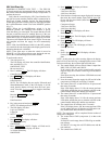
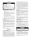
LOG ON TO THE LID DISPLAY — To log on to the LID
display, perform the following procedure:
1. Press 3 and then . The LID display will show:
Controller Password
2. Press . The LID display will show:
Log in to Controller
Enter Password
NOTE: The LID display has two modes: Edit mode and
Status/Maintenance mode. Edit mode allows the user
to change settings on the configurations screens. Status/
Maintenance mode only allows the user to look at the
settings.
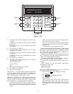
SET
ENTER
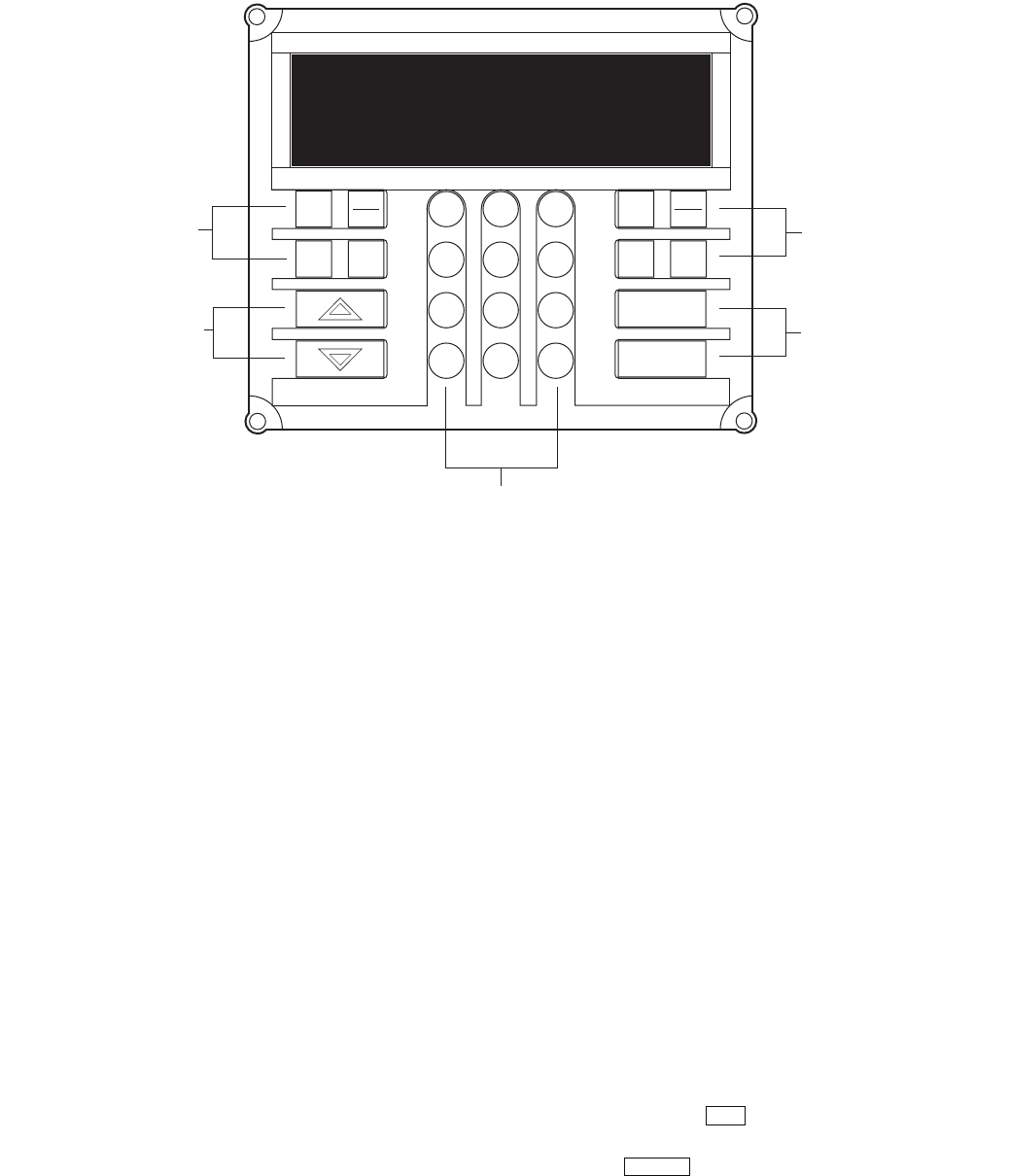
Fig. 32 — LID
ENTER
CLEAR
SRVC
HIST ALGO
TEST
ALRM
3
6
9
1
2
4
5
7
8
0
.
–
STAT
SET
SCHD
EXPN
EDIT
FUNCTION
KEYS
OPERATIVE
KEYS
FUNCTION
KEYS
OPERATIVE
KEYS
NUMERIC KEYS
OMNIZONE VPAC
12:00 02-06-04
a50-7425ef