


11
a50-8206
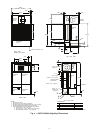
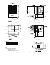
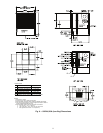
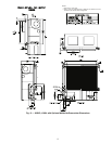
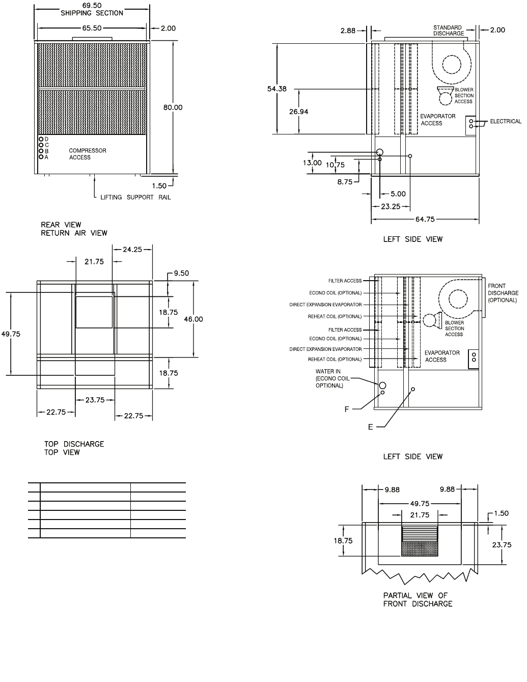
Fig. 9 — 50BVU,X034 (Low-Boy) Dimensions
NOTES:
1. Dimensions in inches.
2. All units are rear return airflow configuration.
3. Recommended condenser match is ONE (1) 09DK034 (50/50 split).
4. Use proper piping practice for remote refrigerant connections. Refer to
Carrier System Design Manual Part 3.
5. Recommended minimum service clearances are as follows:
a. Front and rear — 30 in. (762 mm)
b. Left or right side — 65 in. (1651 mm) for coil removal
c. Side opposite coil removal — 20 in. (508 mm)
CONNECTIONS
REPLACEMENT FILTERS : EIGHT (8) AT 17 x 27 x 4 INCHES.
A LIQUID LINE CIRCUIT 1 7/8 in. OD
B LIQUID LINE CIRCUIT 2 7/8 in. OD
C DISCHARGE LINE CIRCUIT 1 1-1/8 in. OD
D DISCHARGE LINE CIRCUIT 2 1-1/8 in. OD
E CONDENSATE DRAIN 1-1/4 in. FPT
F ECONOMIZER DRAIN 1-1/4 in. FPT
a50-8206