


28
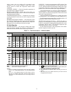
Table 10 — Recommended Cables
NOTE: Conductors and drain wire must be at least 20 AWG
(American Wire Gage), stranded, and tinned copper. Individual
conductors must be insulated with PVC, PVC/nylon, vinyl,
Teflon
®
*, or polyethylene. An aluminum/polyester 100% foil
shield and an outer jacket of PVC, PVC/nylon, chrome vinyl,
or Teflon with a minimum operating temperature range of
–20 C to 60 C is required.
The communication bus shields must be tied together at
each system element. If the communication bus is entirely
within one building, the resulting continuous shield must be
connected to ground at only one single point. If the communi-
cation bus cable exits from one building and enters another
building, the shields must be connected to the grounds at a
lightning suppressor in each building (one point only).
Wiring Control Devices
— Standard controls require no field
wiring.
Standard controls for VAV applications include: duct static
pressure (DSP), duct high static limit switch (DHS), compres-
sor status (CSMUX), supply fan start/stop (SF), and supply fan
speed (SPEED).
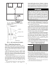
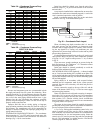
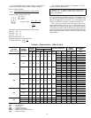
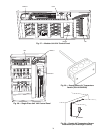
Field-installed devices and the factory-supplied supply air
temperature sensor (required) will be wired to the field termi-
nal block (TB2) provided. Refer to Fig. 26 and the following
descriptions. This terminal is located in the control panel as
shown in Fig. 27 and 28.
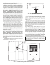
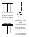
SUPPLY AIR TEMPERATURE SENSOR (SAT) — The sup-
ply air temperature sensor (Fig. 29) is used to measure the
temperature of the air leaving the unit. The sensor should be
located in the supply air duct, about 1 ft from the unit discharge
connection (Fig. 30). On units with 2 fans, locate the sensor ap-
proximately 5 duct diameters downstream from “pair of pants”
duct connection, allowing for adequate mixing of supply air.
Mount the sensor as follows:
1. Remove the cover of the sensor junction box.
2. Drill a
7
/
16
-in. hole at the selected location.
3. Install the sensor through the hole and secure using 2
no. 8 screws (provided). Do not overtighten.
4. Connect the sensor to the control box. Use an 18 or
20 AWG, 2 conductor, twisted pair cable. This cable is
suitable for distances of up to 500 feet.
Connect the field wires to the supply air sensor using wire
nuts or closed end style crimp connectors. Do not cut the
sensor leads. Use the full length of lead supplied on the sensor.
In the control box, remove the jacket from the cable. Route
the sensor wires over to the right hand side of the field terminal
block (TB2). Strip the insulation back about
1
/
4
-in. from each
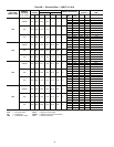
conductor. Connect the two wires to terminals 101 and 102
(SAT) on the terminal board. Polarity is not a consideration.
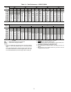
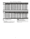
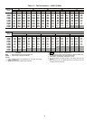
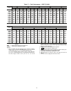
See Table 11 for resistance vs. temperature values.
MANUFACTURER PART NUMBER
Alpha 2413 or 5463
American A22503
Belden 8772
Columbia 02525
Fig. 26 — Field Terminal Block
a50-7164tf
*Teflon is a registered trademark of E.I. du Pont de Nemours and
Company.
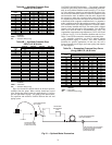
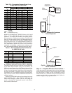
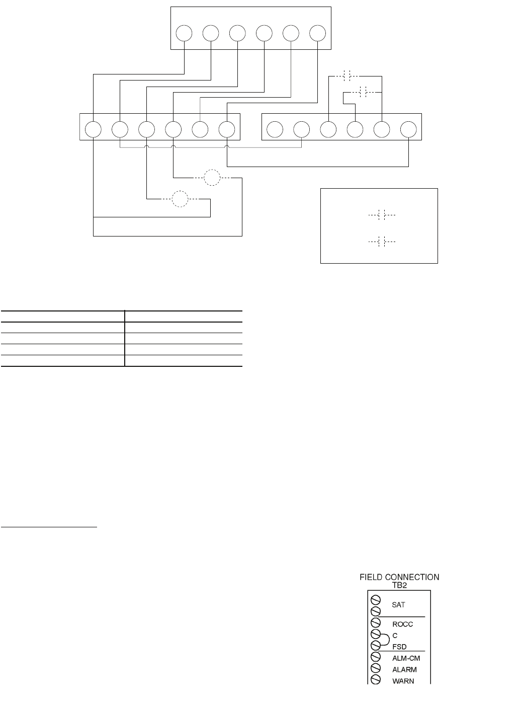
C O Y1 Y3 R G C O Y2 Y4
C O Y1 Y2 R G
PR2
PR1
PR1
PR2
FIELD-SUPPLIED THERMOSTAT
UNIT MODULE ‘A’ UNIT MODULE ‘B’
Remote Condenser Units Only
PR1
PR2
FC1-4 FC1-5
FC1-4 FC1-5
(#1)
(#2)
R
G
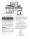
Fig. 25 — Typical Wiring 40 to 60 Ton Units (Two-Stage Cooling)
a50-7273ef
LEGEND
FC — Fan Contactor
PR — Pilot Relay