


49
SERVICE
Compressor Rotation —
To determine whether or not
the compressor is rotating in the proper direction:
1. Connect service gages to suction and discharge pressure
fittings.
2. Energize the compressor.
The suction pressure should drop and the discharge pres-
sure should rise, as is normal on any start-up. If the suc-
tion pressure does not drop and the discharge pressure
does not rise to normal levels:
3. Turn off power to the unit and tag disconnect.
4. Reverse any 2 of the unit power leads.
Reapply power to the unit. The suction and discharge
pressure levels should now move to their normal start-up
levels.
Also, check that the fan is rotating in the proper direction.
NOTE: When the compressor is rotating in the wrong direc-
tion, the unit makes an elevated level of noise and does not
provide cooling.
Fan Motor Replacement — If required, replace the
fan motor with an equal or better type and efficiency motor
with equal horsepower. The motor must be rated for a VFD or
inverter application. Do not change the horsepower unless
there is a system design requirement change and VFD size
analysis.
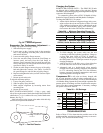
CHECK/CHANGE VFD OUTPUT CURRENT LIMIT —
The VFD provides additional fan motor protection by limiting
the output current to a programmed value. This value has been
factory set according to the factory-installed motor and VFD
sizing options.
If the VFD and/or motor is replaced, the VFD setup mode
parameter "tHr1" should be reprogrammed to the following
calculated values for optimum motor protection and operating
range:
For VFD size about equal to motor:
tHr1 = 100*motor nameplate Amps / VFD rated output Amps
MAINTENANCE
Cleaning Unit Exterior —
Unit exterior panels should
be wiped down using a damp soft cloth or sponge with a mix-
ture of warm water and a mild detergent.
Coil Cleaning — Hot water, steam, and direct expansion
coils must be cleaned at least once a year to maintain peak per-
formance. Dirty coils can contribute to decreased heating or
cooling capacity and efficiency, increased operating costs, and
compressor problems on direct expansion systems. Dirt,
grease, and other oils can also reduce the wettability of the coil
surfaces, which can result in moisture blow-off from cooling
coils and resulting water leakage problems. If the grime on the
surface of the coils becomes wet, which commonly occurs with
cooling coils, microbial growth (mold) can result, causing foul
odors and health related indoor air quality problems.
Coils can become dirty over a period of time, especially
if air filter maintenance is neglected. Coils should be in-
spected regularly and cleaned when necessary. Clean coils
with a vacuum cleaner, fresh water, compressed air, or a
bristle brush (not wire). Do not use high-pressure water or
air. Damage to fins may result. Backflush coil to remove de-
bris. Commercial coil cleaners may also be used to help re-
move grease and dirt. Steam cleaning is NOT recommend-
ed. After cleaning, use a fin comb of the correct fin spacing
when straightening mashed or bent coil fins.
Units installed in corrosive environments should be
cleaned as part of a planned maintenance schedule. In this
type of application, all accumulations of dirt should be
cleaned off the coil.
Inspection — Check coil baffles for tight fit to prevent air
from bypassing the coil. Check panels for air leakage, particu-
larly those sealing the fan and coil compartments. Check for
loose electrical connections, compressor oil levels, proper re-
frigerant charge, and refrigerant piping leaks. Before start-up,
be sure all optional service valves are open.
Air Filters — The 50BV single-piece units come with 1-in.
filters. The standard 1-in. filters provide lower pressure drop
and longer filter service intervals. The 50BV modular units
come with 4-in. filters.
Inspect air filters every 30 days and replace filters as
necessary.
Replacement filters should have a minimum efficiency rat-
ing of MERV 6 per ASHRAE rating procedures and be rated
for up to 625 fpm velocity. Job requirements or local codes
may specify higher minimum ratings.
Condensate Drains — Clean the drain line and unit
drain pan at the start of each cooling season. Check flow by
pouring water into the drain.
Water-Cooled Condensers — Water-cooled condens-
ers may require cleaning of the scale (water deposits) due to
improperly maintained closed-loop water systems. Sludge
build-up may need to be cleaned in an open tower system due
to inducted contaminants.
Local water conditions may cause excessive fouling or pit-
ting of tubes. Condenser tubes should be cleaned at least once a
year, or more often if the water is contaminated.
Proper water treatment can minimize tube fouling and
pitting. If such conditions are anticipated, water treatment
analysis is recommended. Refer to the System Design Manual,
Part 5, for general water conditioning information.
Isolate the supply and return water connections when re-
moving piping to the condenser.
Clean condensers with an inhibited hydrochloric acid solu-
tion. The acid can stain hands and clothing, attack concrete,
and, without inhibitor, can attack steel. Cover surroundings to
guard against splashing. Vapors from vent pipe are not harmful,
but take care to prevent liquid from being carried over by the
gases.
Warm solution acts faster, but cold solution is just as effec-
tive if applied for a longer period.
CAUTION
Improper phase sequence will cause scroll compressor
failure due to reverse rotation.
Signs of miswire are:
• Excessive noise
• Reverse rotation of 3 phase indoor fan
• Rapid temperature rise on suction tube
• No pressure differential
Correct immediately. Shut off power at disconnect
and switch any 2 power leads at unit terminal block or
pigtails.
CAUTION
Follow all safety codes. Wear safety glasses and rubber
gloves when using inhibited hydrochloric acid solution.
Observe and follow acid manufacturer’s instructions.