


27
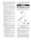
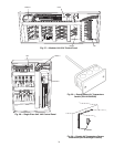
Modular Units
— For units with multiple main air-
conditioning sections, connect the high voltage compressor
power wiring to the line side of the high voltage terminal block
in the second section’s high voltage electrical box. This wiring
is located in the upper portion of the compressor compartment.
Connect the low voltage wiring, located in the compressor
compartment, between the two air conditioning sections using
the quick connects provided.
For the supply fan motor, connect the 3-phase high voltage
wiring, coiled behind the high voltage panel, to the line side of
the supply fan motor terminal block located in the fan compart-
ment. For VAV units, connect the 3-phase high voltage wiring
to the line side of VFD.
For units with multiple fans, connect the control power
wiring with the quick connects provided at the fan compart-
ment junction.
CONTROL WIRING (CV Only) — A standard commercial
thermostat controls constant volume units. These units turn
compressors on or off in response to zone temperature. The
50BV units provide 2 stages of cooling.
50BVC,E,Q020-034 and 50BVT,U,V034 Only
— These
models have 2 independent refrigerant circuits, each capable of
being staged independently. Thermostat wiring is connected to
the 6-position low voltage terminal block located in the unit
electrical box. The 50BV units have a 24-VAC control
transformer, which provides power to the control circuit and to
the thermostat. The thermostat connections and their functions
are as follows:
C Transformer 24-v ac Common
O Reversing Valve (heat pumps only)
Y1 1st Stage Compressor Contactor
Y2 2nd Stage Compressor Contactor
R Transformer 24-v ac Hot
G Indoor Fan Contactor
Select an appropriate commercial thermostat that has 2 stag-
es of cooling control. If the unit is a heat pump, make sure the
thermostat is capable of heat pump control. Any of the
Debonair® series commercial thermostats will meet the re-
quirements, and are available in a variety of attractive styles, in
programmable and non-programmable versions.
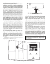
Install the thermostat in the space where the temperature is
being controlled, according to the instructions provided with
the thermostat.
To wire the thermostat:
1. Connect the ‘C’ terminal from the 50BV unit to the ‘C’
terminal on the thermostat.
2. Wire the ‘Y1’ and ‘Y2’ terminals from the 50BV unit
to the ‘Y1’ and ‘Y2’ terminals, respectively, at the
thermostat.
3. Make a connection between the ‘G’ terminal on the unit
and the ‘G’ terminal on the thermostat.
4. Attach a wire from the ‘R’ terminal at the unit to the ‘R’
terminal at the thermostat.
5. 50BVQ and 50BVV ONLY: If the unit is a heat pump,
connect a final wire from terminal ‘O’ on the heat pump
unit to the ‘W1/O/B’ terminal at the thermostat.
Configure the thermostat for heat pump operation using
the installation instructions provided with the thermostat.
Set the reversing valve polarity of the thermostat to ‘O’.
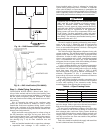
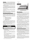
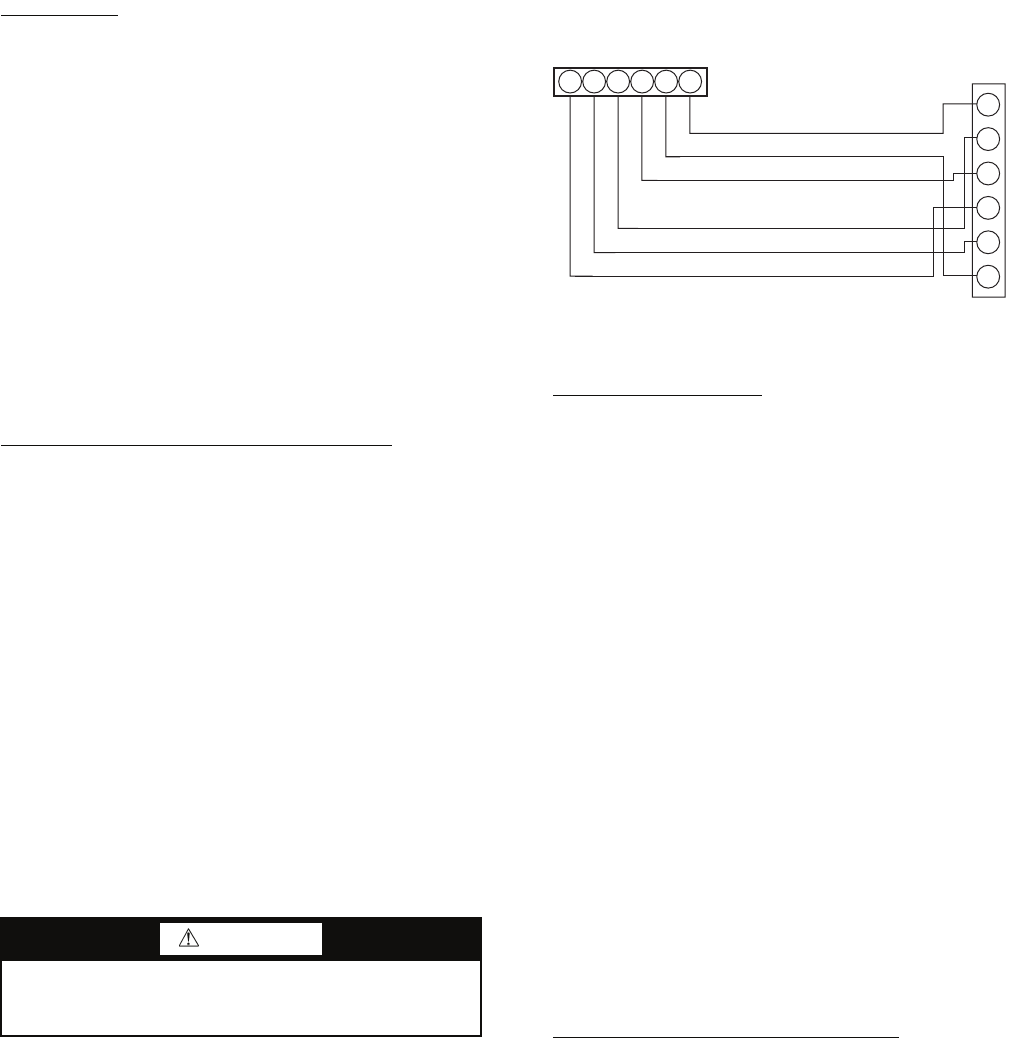
See Fig. 24 for typical thermostat wiring.
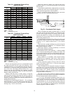
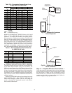
50BVT,U,V044-064 Only
— Units larger than 30 tons have 4
independent refrigerant circuits.
These units can be controlled using a standard commercial,
2-stage thermostat. In this case, the first stage of cooling will
turn on compressors 1 and 2, and the second stage will turn on
compressors 3 and 4. It is also possible to have 4 stages of cool-
ing, using a suitable field-supplied control method.
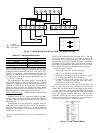
For 2-stage thermostat wiring, refer to Fig. 25. Jumpers
must be installed between the G and O terminals in Modules A
and B. A field-supplied, 24-v pilot relay should be used to en-
ergize Y2 on Module B whenever Y1 is energized on Module
A. Similarly, a field-supplied 24-v pilot relay should be in-
stalled to energize Y4 on Module B whenever Y3 on Module
A is energized (Y2 stage of thermostat calls for cooling).
Finally, verify that transformer phasing is consistent
between Modules A and B.
REMOTE CONDENSER FAN CONTACTOR WIR-
ING — For units up to 30 tons, one remote condenser is
required. Install a field-supplied 24-v pilot relay (Aux relay)
between Y1 and C. This will energize the FC contactor on the
remote condenser whenever there is a call for cooling.
For 40 to 60 ton units, 2 remote condensers are required. Be
sure to make piping connections so that compressors 1 and 2 are
connected to condenser 1, and compressors 3 and 4 are connect-
ed to condenser 2. Use an additional set of NO (normally open)
contacts on PR1 to energize FC1 on condenser 1, and a set of
NO contacts on PR2 to energize FC1 on condenser 2.
CONTROL WIRING (VAV Only) — The VAV units are de-
signed to operate either with a building management system or
stand alone (local control).
Carrier Comfort Network® Control Wiring
— The CC6400
Control Module connects to the Carrier Comfort Network
(CCN) bus in a daisy chain arrangement. Negative pins on
each component must be connected to respective negative pins
and likewise positive pins on each component must be
connected to respective positive pins. The controller signal pins
must be wired to the signal ground pins. Wiring connections
for CCN must be made at the 3-pin plug.
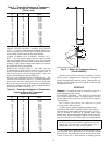
At any baud rate (9600, 19200, 38400 baud), the number of
controllers is limited to 239 devices maximum. Bus length may
not exceed 4000 ft, with no more than 60 total devices on any
1000-ft section. Optically isolated RS-485 repeaters are
required every 1000 ft.
NOTE: Carrier device default is 9600 baud.
The CCN communication bus wiring is field supplied and
field installed. It consists of shielded 3-conductor cable with
drain (ground) wire. The cable selected must be identical to the
CCN communication bus wire used for the entire network. See
Table 10 for cable recommendations.
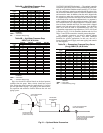
WARNING
Before wiring the thermostat to the unit, make sure that
main power to the unit has been disconnected. Failure to
heed this warning could result in personal injury.
TYPICAL
UNIT
C
G
Y1
O
R
Y2
24 VAC COMMON
FAN RELAY
COMPRESSOR RELAY
HEAT PUMP
24 VAC RETURN
2nd STAGE COMPRESSOR RELAY
Y2
R
W1
Y1
G
C
THERMOSTAT
B
O
Fig. 24 — Typical Wiring 18 to 30 Ton Units
(Two-Stage Cooling Units)
a50-7272ef