


61
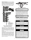
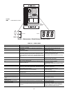
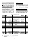
Advanced scroll temperature protection is a form of internal
discharge temperature protection that unloads the scroll com-
pressor when the internal temperature reaches approximately
300 F. At this temperature, an internal bi-metal disk valve
opens and causes the scroll elements to separate, which stops
compression. Suction and discharge pressures balance while
the motor continues to run. The longer the compressor runs un-
loaded, the longer it must cool before the bi-metal disk resets.
See Fig. 66 for approximate reset times.
To manually reset ASTP, the compressor should be stopped
and allowed to cool. If the compressor is not stopped, the motor
will run until the motor protector trips, which occurs up to
90 minutes later. Advanced scroll temperature protection will
reset automatically before the motor protector resets, which
may take up to 2 hours.
Compressor Time Guards
— For compressors, the control
will use a Compressor Minimum OFF Time of 2 minutes or a
Compressor Minimum ON Time of 3 minutes.
High Discharge Gas Temperature Protection
— Units
equipped with digital compressors have an additional thermis-
tor located on the discharge line, If discharge temperature ex-
ceeds 265 F (129.4 C), the digital compressor will be shut off.
Alarms will also occur if the current sensor board malfunc-
tions or is not properly connected to its assigned digital input. If
the compressor is commanded OFF and the current sensor
reads ON, an alert is generated. This will indicate that a com-
pressor contactor has failed closed. In this case, a special mode,
Compressor Stuck on Control, will be enabled and all other
compressors will be turned off. An alarm will then be enabled
to indicate that service is required. Outdoor fans will continue
to operate. The first outdoor fan stage is turned on immediately.
The other stages of fan will be turned on as required by SCT.
Low Saturated Suction
— Several conditions can lead to low
saturated suction alarms. The controls have several override
modes built in which will attempt to keep the unit from
shutting down. Low airflow, low refrigerant charge and
plugged filter driers are the main causes for this condition. To
avoid permanent damage, do NOT repeatedly reset these alert
and/or alarm conditions without identifying and correcting the
cause(s).
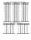
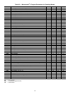
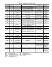
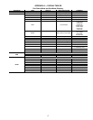
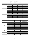
Alarms and Alerts — These are warnings of abnormal
or fault conditions, and may cause either one circuit or the
whole unit to shut down. They are assigned code numbers as
described in Table 26.
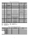
Automatic alarms will reset without operator intervention if
the condition corrects itself. The following method must be
used to reset manual alarms (refer to Table 27):
Before resetting any alarm, first determine the cause of the
alarm and correct it. After determining and correcting the cause
of the alarm, enter the Alarm mode indicated by the LED on
the side of the scrolling marquee display. Press and
until the sub-menu item RCRN “RESET ALL CURRENT
ALARMS” is displayed. Press . The control will
prompt the user for a password, by displaying PASS and
WORD. Press to display the default password, 1111.
Press for each character. If the password has been
changed, use the arrow keys to change each individual charac-
ter. Toggle the display to “YES” and press . The
alarms will be reset.
DIAGNOSTIC ALERT CODES AND POSSIBLE
CAUSES
T048 (Circuit A Compressor Availability Alert)
T049 (Circuit B Compressor Availability Alert) — Alert
codes 048 and 049 are for circuits A and B respectively. These
alerts occur when two compressors are unavailable to run on a
3 compressor circuit. This alert can only occur on single circuit
unit sizes 040-060 and three compressor circuit unit sizes 70-
100. The control ensures proper oil return by insuring a circuit
does not operate with one compressor for longer than one hour
of cumulative run time.
COMPRESSOR FAILURE ALERTS
T051, T052, T053 (Circuit A Compresser Failures)
T055, T056, T057 (Circuit B Compressor Failures) — Alert
codes 051, 052, 053, 55, 56 and 057 are for compressors A1,
A2, A3, B1, B2, and B3 respectively. These alerts occur when
the current sensor (CS) does not detect compressor current dur-
ing compressor operation. When this occurs, the control turns
off the compressor.
If the current sensor board reads OFF while the compressor
relay has been commanded ON, an alert is generated.
POSSIBLE CAUSES
Compressor Overload
— Either the compressor internal over-
load protector is open or the external overload protector (Kri-
wan module) has activated. The external overload protector
modules are mounted in the compressor wiring junction box.
Temperature sensors embedded in the compressor motor wind-
ings are the inputs to the module. The module is powered with
24 vac from the units main control box. The module output is a
normally closed contact that is wired in series with the com-
pressor contactor coil. In a compressor motor overload condi-
tion, contact opens, deenergizing the compressor contactor.
Low Refrigerant Charge
— If the compressor operates for an
extended period of time with low refrigerant charge, the com-
pressor ASTP device will open, which will cause the compres-
sor to trip on its overload protection device.
Circuit Breaker Trip
— The compressors are protected from
short circuit by a breaker in the control box.
Fig. 66 — Recommended Minimum Cool Down
Time After Compressor is Stopped*
0
10
20
30
40
50
60
70
80
90
100
110
120
0 102030405060708090
Compressor Unloaded Run Time (Minutes)
Recommended Cooling Time
(Mi
nut
es)
*Times are approximate.
NOTE: Various factors, including high humidity, high ambient temperature,
and the presence of a sound blanket will increase cool-down times.
ENTER
ENTER
ENTER
ENTER
ENTER
Fig. 65 — Advanced Scroll Temperature
Protection Label