


16
25242322212019181716151413
REMOTE
ON/OFF
LVT
TERMINAL
STRIP
121110987654321
ALM
R
FS 1
LLSV-A
SEE NOTE 6
SAT
*
MAT/RAT
*
LLSV-B
†
25242322212019181716151413
LVT
TERMINAL
STRIP
121110987654321
DEMAND LIMIT STEP 1
DEMAND LIMIT STEP 2
DEMAND
LIMIT
4-20 mA
+
–
COOLING
SETPOINT/
CAPACITY
REQUESTED
4-20 mA
+
–
TEMP
RESET
4-20 mA
+
–
a38-7128
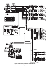
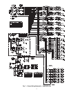
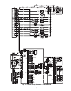
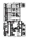
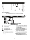
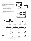
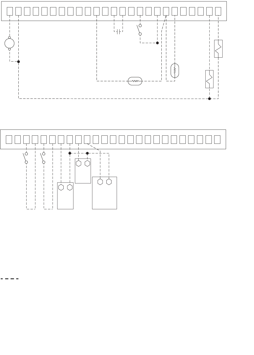
Fig. 16 — Variable Air Volume Application Wiring Diagram, Sizes 025-100
*See Fig. 12 for MAT/RAT and SAT location.
†Not required for single circuit units.
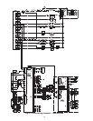
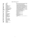
Fig. 17 — Optional Energy Management Module Wiring
a38-7129
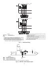
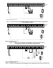
Legend and Notes for Fig. 13-17
LEGEND
NOTES:
1. Factory wiring is in accordance with UL 1995 standards. Field
modifications or additions must be in compliance with all appli-
cable codes.
2. All units or modules have single point primary power connec-
tion. Main power must be supplied from a field or factory-
supplied disconnect.
3. Wiring for main field supply must be rated 75 C. Use copper
conductors only.
a. Incoming wire size range for terminal block with MCA (mini-
mum circuit amps) up to 175 amps is 14 AWG (American
Wire Gage) to 2/0.
b. Incoming wire size range for terminal block with MCA from
175.1 amps to 420 amps is 2 AWG to 600 kcmil.
c. Incoming wire size range for non-fused disconnect with MCA
up to 100 amps is 14 AWG to 1/0.
d. Incoming wire size range for non-fused disconnect with MCA
from 100.1 amp to 200 amps is 6 AWG to 350 kcmil.
e. Incoming wire size range for non-fused disconnect with MCA
from 200.1 amp to 450 amps is 3/0 to 500 kcmil.
4. Terminals 1 and 2 of the LVT are for the alarm relay. The maxi-
mum load allowed for the alarm relay is 5-va sealed and 10-va
inrush at 24-v. Field power supply is not required.
5. Refer to certified dimensional drawings for exact locations of
the main power and control power entrance locations.
6. Terminals 24, 25, and 2 of the LVT are for the control of the
field-supplied LLSV. The maximum load allowed for the LLSV
is 15-va sealed and 30-va inrush at 24-v. Field power supply is
not required.
7. LLSV (24-v) should be 15-va maximum per valve as required.
8. Installation of fan status switch (FS1) is recommended.
9. The contacts for remote ON/OFF, fan status, and demand limit
options must be rated for dry circuit application capable of han-
dling a 24-vac load up to 50 mA.
ALM R — Alarm Relay (24-v), 5-va Maximum
COOL1 — Thermostat Stage 1 (24-v)
COOL2 — Thermostat Stage 2 (24-v)
FS1 — Fan Status Switch (24-v)
LLSV — Liquid Line Solenoid Valve
LVT — Low Voltage Terminal
MAT — Mixed Air Temperature Sensor
RAT — Return Air Temperature Sensor
SA — Set Point Adjustment (T-56, T-59)
SAT — Supply Air Temperature Sensor
SPT — Space Temperature Sensor (T-55, T-56, T-59)
Field Control Wiring