


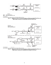
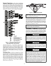
54
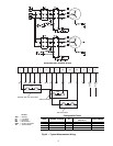
Pressure Transducers — The suction and discharge
transducers are different part numbers and can be distinguished
by the color of the transducer body, suction (yellow) and dis-
charge (red). Figures 59 and 60 shows typical location of pres-
sure transducers on each circuit. No pressure transducer cali-
bration is required. The transducers operate on a 5 vdc supply,
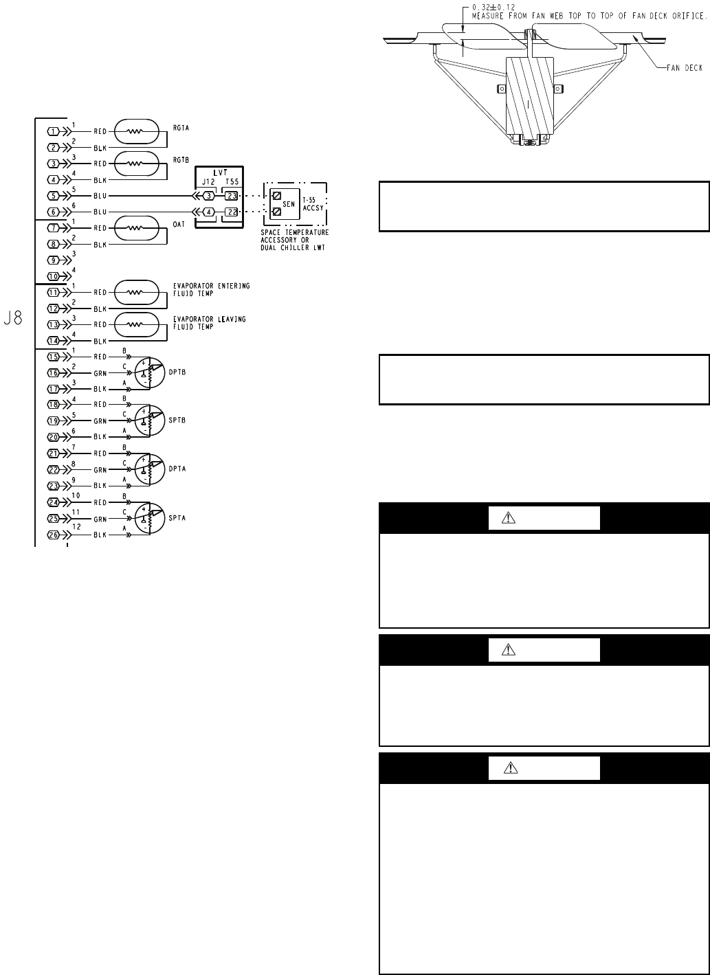
which is generated by the main base board (MBB). See Fig. 61
for transducer connections to the J8 connector on the MBB.
TROUBLESHOOTING — If a transducer is suspected of be-
ing faulty, first check supply voltage to the transducer. Supply
voltage should be 5 vdc ± 0.2 v. If supply voltage is correct,
compare pressure reading displayed on the scrolling marquee
display module against pressure shown on a calibrated pressure
gauge. Pressure readings should be within ± 15 psig. If the
two readings are not reasonably close, replace the pressure
transducer.
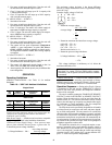
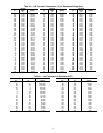
Condenser Fans — Each fan is supported by a formed
wire mount bolted to a fan deck and covered with a wire guard.
METAL FANS — The exposed end of fan motor shaft is pro-
tected from weather by grease and a rubber boot. If fan motor
must be removed for service or replacement, be sure to re-
grease fan shaft and reinstall fan guard. For proper perfor-
mance, fan web should be 0.32 in. (8 mm) below top of orifice
on the fan deck to top of the fan hub. (See Fig. 62.) Tighten set
screws to 15 ± 1 ft-lb (20 ± 1.3 N-m). Figure 62 shows the
proper position of mounted fan.
LOW SOUND FAN — A shroud and a wire guard provide
protection from the rotating fan. The exposed end of the fan
motor shaft is protected from weather by grease. If fan motor
must be removed for service or replacement, be sure to re-
grease fan shaft and reinstall fan guard. The fan motor has a
step in the motor shaft. For proper performance, fan should be
positioned such that it is securely seated on this step. Tighten
the bolt to 15 ± 1 ft-lb (20 ± 1.3 N·m).
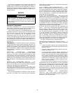
Motormaster
®
V Controller — The optional or acces-
sory Motormaster V controller uses an input signal from the
AUX board. See Fig. 63. The controller is factory configured
and requires no field programming. If a situation arises where
the drive does not function properly, the information provided
below and in Table 22 can be used to troubleshoot the drive.
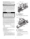
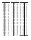
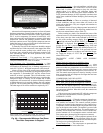
Fig. 61 — Thermistor Connections to
Main Base Board, J8 Connector
26
25
24
23
22
17
16
15
14
13
12
11
10
9
8
7
6
3
1
3
1
3
1
6
2
4
2
4
2
12
11
21
20
19
18
10
9
8
7
6
5
4
5
4
3
2
1
4
2
1
3
5
J8
BLK
RED
LVT
4
3
22
23
T-55
ACCSY
SEN
OAT
BLU
BLU
BLK
RED
RGTB
BLK
RED
RGTA
SPTB
-
+
DPTB
-
+
A
C
B
A
C
B
GRN
RED
BLK
GRN
RED
BLK
SPTA
-
+
DPTA
-
+
A
C
B
A
C
B
GRN
RED
BLK
GRN
RED
BLK
BLK
RED
EVAPORATOR ENTERING
FLUID TEMP
BLK
RED
EVAPORATOR LEAVING
FLUID TEMP
SPACE TEMPERATURE
ACCESSORY OR
DUAL CHILLER LWT
J12 T55
LEGEND
ACCSY — Accessory
DPT — Discharge Pressure Transducer
LVT — Low Voltage Terminal
LWT — Leaving Fluid Temperature
OAT — Outdoor Air Temperature Sensor
RGT — Return Gas Temperature Sensor
SEN — Sensor Terminal Block
SPT — Space Temperature Sensor
transducer.eps
in job folder (WIP)
IMPORTANT: Check for proper fan rotation (clockwise
when viewed from above). If necessary, switch any
2 power leads to reverse fan rotation.
IMPORTANT: Check for proper fan rotation (counter-
clockwise when viewed from above). If necessary, switch
any 2 power leads to reverse fan rotation.
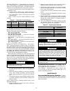
WARNING
Hazard of electrical shock! Wait three minutes after discon-
necting incoming power before servicing drive. Capacitors
retain charge after power is removed. Drive assembly
includes externally mounted current limiting resistors. Use
extreme caution when servicing the drive. Failure to com-
ply could result in possible personal injury.
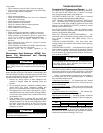
WARNING
When configured as shown below, this equipment is
designed to start when it receives line power. Ensure that
all personnel are clear of fans and guards are installed
before applying power. Failure to comply could result in
possible personal injury.
CAUTION
If input power has not been applied to the drive for a period
of time exceeding three years (due to storage, etc.), the
electrolytic DC bus capacitors within the drive can change
internally, resulting in excessive leakage current. This can
result in premature failure of the capacitors if the drive is
operated after such a long period of inactivity or storage. In
order to reform the capacitors and prepare the drive for
operation after a long period of inactivity, apply input
power to the drive for 8 hours prior to actually operating
the motor. Before attempting to operate the drive, motor,
and driven equipment, be sure all procedures pertaining to
installation and wiring have been properly followed. Fail-
ure to comply could result in equipment damage.
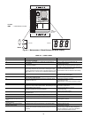
Fig. 62 — Mounted Fan Position
fan height.eps in
job folder (WIP)