


59
TROUBLESHOOTING — Troubleshooting the Motormas-
ter
®
V control requires a combination of observing system op-
eration and VFD display information. The MMV should fol-
low the 4 to 20 mA signal from the ComfortLink™ controls.
The speed command from the ComfortLink controls can be
monitored in 2 ways:
1. Variables VH.PA, VH.PB in the "outputs" submenu of
ComfortLink - given as a percentage of 4 to 20 mA range.
2. P56 in Motormaster V shows 4-20 mA input in percent of
maximum input.
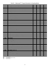
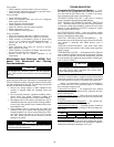
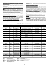
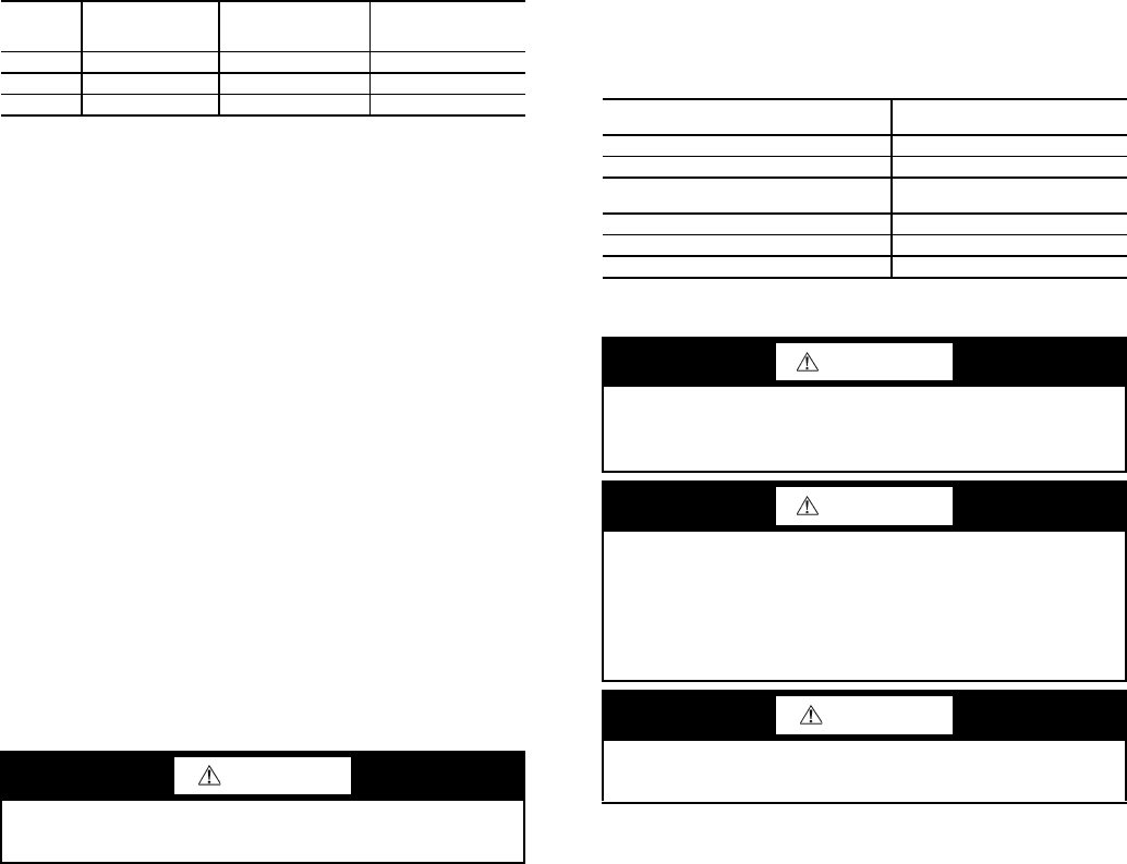
Refer to Table 24 for the variable definitions of each
controller.
Table 24 — Controller Cross-Reference
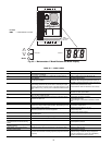
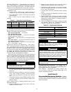
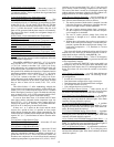
The MMV also provides real time monitoring of key in-
puts and outputs. The collective group is displayed through pa-
rameters 50-56 and all values are read only.
• P50: FAULT HISTORY — Last 8 faults
• P51: SOFTWARE version
• P52: DC BUS VOLTAGE — in percent of nominal.
Usually rated input voltage x 1.4.
• P54: LOAD — in percent of drives rated output current
rating
• P55: VDC INPUT — in percent of maximum input: 50
will indicate full scale which is 5 v
• P56: 4-20 mA INPUT — in percent of maximum input:
20% = 4 mA, 100% = 20 mA
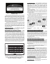
REPLACING DEFECTIVE MODULES — The Comfort-
Link
™
replacement modules are shown in Table 25. If the main
base board (MBB) has been replaced, verify that all configura-
tion data is correct. Follow the Configuration mode table and
verify that all items under sub-modes UNIT, OPT1 and OPT2
are correct. Any additional field-installed accessories or op-
tions (RSET, SLCT sub-modes) should also be verified as well
as any specific time and maintenance schedules.
Refer to the Start-Up Checklist for 38AP units (completed
at time of original start-up) found in the job folder. This infor-
mation is needed later in this procedure. If the checklist does
not exist, fill out the current information in the Configuration
mode on a new checklist. Tailor the various options and config-
urations as needed for this particular installation.
1. Check that all power to unit is off. Carefully disconnect
all wires from the defective module by unplugging its
connectors.
2. Remove the defective module by removing its mounting
screws with a Phillips screwdriver, and removing the
module from the control box. Save the screws for later
use.
3. Verify that the instance jumper (MBB) or address switch-
es (all other modules) exactly match the settings of the
defective module.
NOTE: Handle boards by mounting standoffs only to avoid
electrostatic discharge.
4. Package the defective module in the carton of the new
module for return to Carrier.
5. Mount the new module in the unit’s control box using a
Phillips screwdriver and the screws saved in Step 2.
6. Reinstall all module connectors. For accessory Naviga-
tor™ device replacement, make sure the plug is installed
at LVT in the LEN connector.
7. Carefully check all wiring connections before restoring
power.
8. Verify the ENABLE/OFF/REMOTE CONTACT switch
is in the OFF position.
9. Restore control power. Verify that all module red LEDs
blink in unison. Verify that all green LEDs are blinking
and that the scrolling marquee or Navigator display is
communicating correctly.
10. Verify all configuration information, settings, set points
and schedules. Return the ENABLE/OFF/REMOTE
CONTACT switch to its previous position.
Table 25 — Replacement Modules
Compressors
COMPRESSOR REPLACEMENT — To change out a
faulty compressor, refer to the compressor replacement proce-
dure included with the new compressor.
OIL CHARGE — Compressors are factory charged with
110 oz of POE oil. Refer to Oil Charge section page 47 for
proper oil and charge procedure.
MAINTENANCE
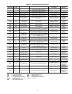
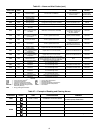
Recommended Maintenance Schedule —
The fol-
lowing are only recommended guidelines. Jobsite conditions
may dictate that maintenance schedule is performed more often
than recommended.
CONTROL
SIGNAL
VH.PA, VH.PB
(COMFORTLINK)
4-20 mA
INPUT (P56,
MOTORMASTER V)
VFD SPEED
(MOTORMASTER V)
4 mA 0% 20% 8 Hz
12 mA 50% 60% 26 Hz
20 mA 100% 100% 60 Hz
CAUTION
Electrical shock can cause personal injury. Disconnect all
electrical power before servicing.
MODULE
REPLACEMENT PART NO.
(with Software)
Main Base Board (MBB) 38AP501672
Scrolling Marquee Display HK50AA031
Energy Management
Module (EMM)
30GT515218
Navigator Display HK50AA033
Compressor Expansion Board HK50AA027
Auxiliary Board 32GB500442EE
WARNING
Do not supply power to unit with compressor cover
removed. Failure to follow this warning can cause a fire,
resulting in personal injury or death.
WARNING
Exercise extreme caution when reading compressor cur-
rents when high-voltage power is on. Correct any of the
problems described below before installing and running a
replacement compressor. Wear safety glasses and gloves
when handling refrigerants. Failure to follow this warning
can cause fire, resulting in personl injury or death.
CAUTION
Do not manually operate contactors. Serious damage to the
machine may result.