


34
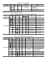
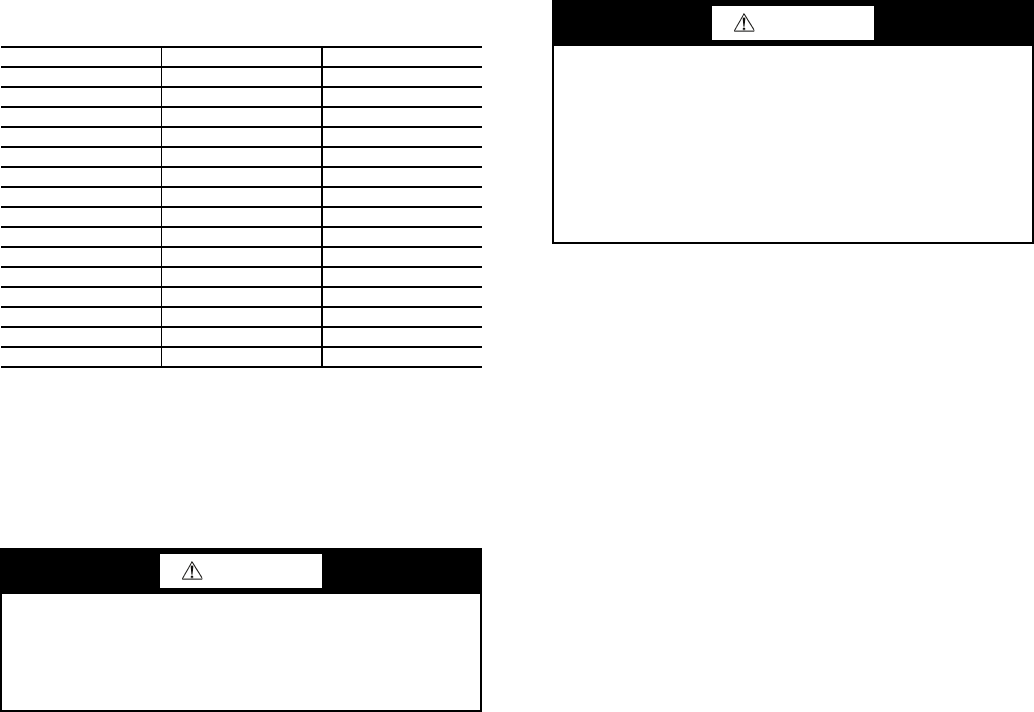
Table 15 — Preliminary Puron Refrigerant (R-410A)
Charge, lb (kg)
NOTES:
1. Preliminary charge is based on 25 ft (7.6 m) of interconnecting liquid line
piping between indoor and outdoor units.
2. For liquid line piping longer than 25 ft (7.6 m), use the following
information:
1
/
2
in. (12.7 mm) liquid line — 0.6 lb per 10 linear ft (0.27 kg per 3 m)
5
/
8
in. (15.9 mm) liquid line — 1.0 lb per 10 linear ft (0.45 kg per 3 m)
7
/
8
in. (22.2 mm) liquid line — 2.0 lb per 10 linear ft (0.91 kg per 3 m)
1
1
/
8
in. (28.6 mm) liquid line — 3.5 lb per 10 linear ft (1.59 kg per 3 m)
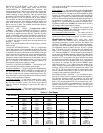
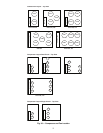
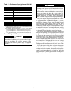
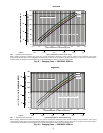
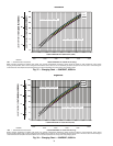
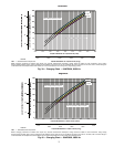
Adjust Refrigerant Charge
Due to the compact design of microchannel heat exchang-
ers, refrigerant charge is reduced significantly. As a result,
charging procedures for MCHX units require very accurate
measurement techniques. Charge should be added in small
increments. Using cooling charging charts provided, add or
remove refrigerant until conditions of the chart are met. As
conditions get close to the point on the chart, add or remove
charge in
1
/
4
lb increments until complete. Ensure that all fans
are on and all compressors are running when using charging
charts. If charging at low outdoor ambient, the condenser coil
can be partially blocked in order to increase head pressure.
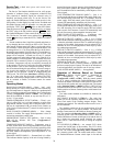
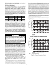
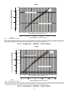
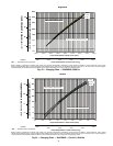
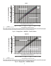
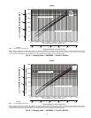
With all fans operating and all compressors on the circuit
being serviced operating at full capacity, adjust the refrigerant
charge in accordance with the unit charging charts in Fig. 35-
56. Charge vapor into compressor low-side service port located
on the suction service valve. Measure pressure at the liquid line
service valve, making sure a Schrader depressor is used. Also,
measure liquid line temperature as close to the liquid service
valve as possible. Add charge until the pressure and tempera-
ture conditions of the charging chart curve are met. If liquid
pressure and temperature point fall above curve, add charge. If
liquid pressure and temperature point fall below curve, reduce
the charge until the conditions match the curve.
If the sight glass is cloudy, check refrigerant charge again.
See Fig. 57 and 58. Ensure all fans and compressors on the cir-
cuit being serviced are operating. Also ensure maximum allow-
able liquid lift has not been exceeded. If the sight glass is
cloudy, a restriction could exist in the liquid line. Check for a
plugged filter drier or partially open solenoid valve. Replace or
repair, as needed.
38AP UNIT SIZE CIRCUIT A CIRCUIT B
38APS025 24 (10.9) —
38APD025 12 (5.6) 12 (5.6)
38APS027 26 (11.6) —
38APD027 13 (6.0) 13 (6.0)
38APS030 29 (12.9) —
38APD030 14 (6.5) 14 (6.5)
38APS040 39 (17.7) —
38APD040 21 (9.5) 17 (7.8)
38APS050 48 (21.5) —
38APD050 22 (9.9) 26 (11.6)
38APD060 27 (12.1) 29 (12.9)
38APD070 29 (12.9) 33 (15.1)
38APD080 29 (12.9) 46 (20.7)
38APD090 39 (17.7) 46 (20.7)
38APD100 46 (20.7) 46 (20.7)
CAUTION
Never charge liquid into the low pressure side of system.
Do not overcharge. During charging or removal of refriger-
ation, be sure indoor fan system is operating. Failure
to comply could result in personal injury or equipment
damage.
CAUTION
Charging procedures for MCHX (microchannel heat
exchanger) units require very accurate measurement tech-
niques. Charge should be added in small increments. Using
cooling charging charts provided, add or remove refriger-
ant until conditions of the chart are met. As conditions get
close to the point on the chart, add or remove charge in
1
/
4
lb increments until complete. Ensure that all fans are on
and all compressors are running when using charging
charts. Failure to comply may result in equipment damage.