


47
Check Compressor Oil Level — After adjusting the
refrigerant charge, allow each circuit to run fully loaded for
20 minutes. Stop the compressors and check the oil level. Oil
level should be
1
/
8
to
3
/
8
up on the sight glass.
Add oil only if necessary to bring the oil into view in the
sight glass. If oil is added, run the circuit for an additional
10 minutes, then stop and check oil level. If the level remains
low, check the piping system for proper design for oil return;
also, check the system for leaks. If checking the oil level with
unit running in part load, let unit run one hour, then run at full
load for 10 minutes. If oil does not return to acceptable sight
glass levels, check for correct suction piping and line sizing.
Final Checks — Ensure all safety controls are operating,
control panel covers are on, and the service panels are in place.
Oil Charge
Puron systems use a polyol ester (POE) oil. Use only Carri-
er approved compressor oil. Oil should be visible in compres-
sor oil sight glass. An acceptable oil level is from
1
/
8
to
3
/
8
of
sight glass. All compressors must be off when checking oil lev-
el. Recommended oil level adjustment method is as follows:
ADD OIL — Recover charge from the outdoor section of the
unit and isolate the condensing unit using the liquid and suction
service valves. Add oil to suction line Schrader valve on tan-
dem compressors sets and the compressor Schrader on the trio
and single compressor circuits. (See Fig. 59 and 60.) When oil
can be seen at the bottom of the sight glass, add oil in 5 oz in-
crements which is approximately
1
/
8
in oil level. Run all com-
pressors for 20 minutes then shut off to check oil level. Repeat
procedure until acceptable oil level is present.
NOTE: Use only Carrier approved compressor oil. Approved
sources are:
Totaline . . . . . . . . . . . . . . . . . . . . . . .3MAF POE P903-1601
Mobil. . . . . . . . . . . . . . . . . . . . . . . . . . .EAL Arctic 32-3MA
Uniqema . . . . . . . . . . . . . . . . . . . . . . . . . . . . . . RL32-3MAF
Do not reuse oil that has been drained out, or oil that has
been exposed to atmosphere.
Actual Start-Up
NOTE: Refer to Start-Up Checklist on pages CL-1 to CL-5.
Actual start-up should be done only under supervision of a
qualified refrigeration mechanic.
VAV APPLICATIONS — C.TYP = 1 and 9
1. Start indoor fan motor.
2. Fan status switch input should close. Note the unit will
not start unless the Fan Status input is closed.
3. Unit C.TYP = 1: Using the scrolling marquee display,
set leaving set point (Set Point COOL CSP.1). Unit
C.TYP = 9: Using the 4 to 20mA input, set the control
point (Run Status VIEW CTPT) for leaving set
point.
4. Turn ENABLE/OFF/REMOTE CONTACT switch to
ENABLE position.
5. If supply air temperature is greater than the control point
the unit will start to stage up.
CV APPLICATION — C.TYP = 4
1. Start indoor fan motor.
IMPORTANT: Oil level should only be checked when the
compressors are off.
CAUTION
The compressor in a Puron
®
refigerant (R-410A) system
uses a polyol ester (POE) oil. This is extremely hygro-
scopic, meaning it absorbs water readily. POE oils can
absorb 15 times as much water as other oils designed for
HCFC and CFC refrigerants. Take all necessary precau-
tions to avoid exposure of the oil to the atmosphere. Failure
to do so could result in possible equipment damage.
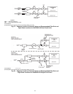
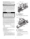
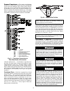
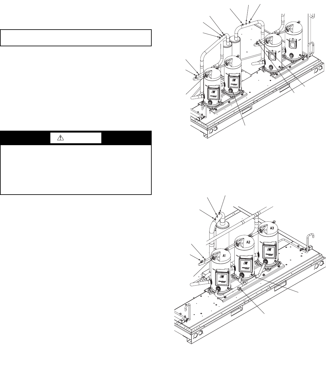
Fig. 60 — Typical Trio Compressor Assembly
LEGEND
DPT — Discharge Pressure Transducer
DTT — Discharge Temperature Thermistor
HPS — High Pressure Switch
RGT — Return Gas Temperature Sensor
SPT — Space Temperature Sensor
OIL SIGHT
GLASS
HPS B
DPT B
SUCTION
SCHRADER A
SUCTION
SCHRADER B
RGT A
HPS A
DPT A
DTT A
SPT A
RGT B SPT B
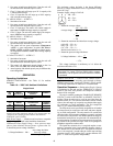
Fig. 59 — Typical Tandem Compressor Assembly
LEGEND
DPT — Discharge Pressure Transducer
DTT — Discharge Temperature Thermistor
HPS — High Pressure Switch
RGT — Return Gas Temperature Sensor
SPT — Space Temperature Sensor
SUCTION
SCHRADER A
OIL SIGHT
GLASS
RGT A
HPS A
DPT A
DTT A
SPT A
OIL ADD
LOCATION