


60
Every month:
• Check condenser coils for debris, clean as necessary.
• Check moisture indicating sight glass for possible refrig-
erant loss and presence of moisture.
Every 3 months:
• Check refrigerant charge.
• Check all refrigerant joints and valves for refrigerant
leaks, repair as necessary.
• Check fan status switch operation.
• Check condenser coils for debris.
• Check all condenser fans for proper operation.
• Check compressor oil level.
• Check crankcase heater operation.
Every 12 months:
• Check all electrical connections, tighten as necessary.
• Inspect all contactors and relays, replace as necessary.
• Check accuracy of thermistors, replace if greater than
± 2° F (1.2° C) variance from calibrated thermometer.
• Obtain and test an oil sample. Change oil only if
necessary.
• Check refrigerant filter driers for excessive pressure
drop, replace as necessary.
• Check condition of condenser fan blades and ensure they
are securely fastened to the motor shaft.
• Perform service test to confirm operation of all
components.
Microchannel Heat Exchanger (MCHX) Con-
denser Coil Maintenance and Cleaning
Recommendations
Routine cleaning of coil surfaces is essential to maintain
proper operation of the unit. Elimination of contamination and
removal of harmful residues will greatly increase the life of the
coil and extend the life of the unit. The following steps should
be taken to clean MCHX condenser coils:
1. Remove any foreign objects or debris attached to the
coreface or trapped within the mounting frame and
brackets.
2. Put on personal protective equipment including safety-
glasses and/or face shield, waterproof clothing and
gloves. It is recommended to use full coverage clothing.
3. Start high pressure water sprayer and purge any soap or
industrial cleaners from sprayer before cleaning condens-
er coils. Only clean, potable water is authorized for clean-
ing condenser coils.
4. Clean condenser face by spraying the core steady and
uniformly from top to bottom while directing the spray
straight toward the core. Do not exceed 900 psig or 30 de-
gree angle. The nozzle must be at least 12 in. from the
core face. Reduce pressure and use caution to prevent
damage to air centers.
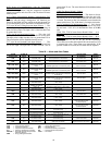
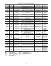
TROUBLESHOOTING
Complete Unit Stoppage and Restart —
Possi-
ble causes for unit stoppage and reset methods are shown be-
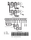
low. (See Table 26 also.) Refer to Fig. 1-3 and 8-17 for compo-
nent arrangement and control wiring diagrams.
GENERAL POWER FAILURE — After power is restored,
restart is automatic through normal MBB start-up.
UNIT ENABLE-OFF-REMOTE CONTACT SWITCH IS
OFF — When the switch is OFF, the unit will stop immediate-
ly. Place the switch in the ENABLE position for local switch
control or in the REMOTE CONTACT position for control
through remote contact closure.
FAN STATUS INPUT OPEN — After the problem causing
the fan status input to be open has been corrected, reset is auto-
matic by closing the fan status input.
OPEN 24-V CONTROL CIRCUIT BREAKER(S) — De-
termine the cause of the failure and correct. Reset circuit break-
er(s). Restart is automatic after MBB start-up cycle is
complete.
COOLING LOAD SATISFIED — Unit shuts down when
cooling load has been satisfied. Unit restarts when required to
satisfy set point.
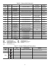
THERMISTOR FAILURE — If a thermistor fails in either an
open or shorted condition, the unit will be shut down. Replace
SAT or RAT as required. Unit restarts automatically, but must
be reset manually by resetting the alarm with the scrolling mar-
quee as shown in Table 27.
COMPRESSOR SAFETIES — The 38AP units with Com-
fortLink™ controls include a compressor protection board that
protects the operation of each of the compressors. Each board
senses the presence or absence of current to each compressor.
If there is a command for a compressor to run and there is
no current, then one of the following safeties or conditions
have turned the compressor off:
Compressor Overcurrent
— All compressors have internal
line breaks or a motor protection device located in the com-
pressor electrical box.
Compressor Short Circuit
— There will not be current if the
compressor circuit breaker that provides short circuit protection
has tripped.
Compressor Motor Over Temperature
— The internal line-
break or over temperature switch has opened.
High-Pressure Switch Trip
— The high pressure switch has
opened. Below are the factory settings for the fixed high pres-
sure switch.
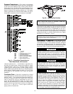
ASTP Protection Trip
— All non-digital Copeland compres-
sors are equipped with an advanced scroll temperature protec-
tion (ASTP). A label located above the terminal box identifies
models that contain this technology. See Fig. 65.
CAUTION
Do not apply any chemical cleaners to MCHX condenser
coils. These cleaners can accelerate corrosion and damage
the coil.
CAUTION
Excessive water pressure will fracture the braze between
air centers and refrigerant tubes.
CAUTION
If unit stoppage occurs more than once as a result of any of
the safety devices listed, determine and correct cause
before attempting another restart.
38AP UNIT
SIZE
CUTOUT CUT-IN
psig kPa psig kPa
025-100 650 4482 500 3447