


49
For all units, if temperature reset is used, the unit controls to
a higher leaving temperature as the building load reduces. If
demand limit is used, the unit may temporarily be unable to
maintain the desired leaving-air temperature because of im-
posed power limitations. Loading sequence for compressors is
shown in Table 8.
SERVICE
Electronic Components
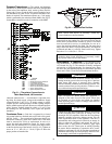
CONTROL COMPONENTS — Unit uses an advanced elec-
tronic control system that normally does not require service.
For details on controls refer to Operating Data section.
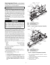
Access to the compressors is through latched panels from
beneath the control box on the unit sizes 025-060 and on each
end of the unit on sizes 070-100. The front door(s) provide
access to the compressor(s) and all components of the
refrigeration system. For unit sizes 025-030, access to the
controls is through the upper latched outer door above the com-
pressor access door. Similarly, the upper center latched door on
sizes 040-060 gives access to the controls. Inner panels are se-
cured in place and should not be removed unless all power to
the unit is off.
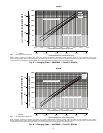
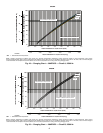
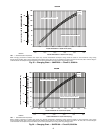
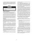
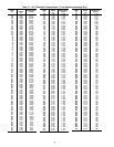
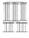
Thermistors — Electronic control uses up to 7 thermistors
to sense temperatures used to control operation of the unit. The
standard unit comes with return gas temperature (RGT) and
outside air temperature (OAT) thermistors. These thermistors
are 5 k thermistors, identical in their temperature and voltage
drop performance. Resistance at various temperatures is listed
in Tables 17-21.
DISCHARGE TEMPERATURE THERMISTOR
(DTT) — This sensor is only used on units with a digital
compressor. The sensor is mounted on the discharge line close
to the discharge of the digital compressor. It attaches to the dis-
charge line using a spring clip and protects the system from
high discharge gas temperature when the digital compressor is
used. This sensor is a 86 k thermistor connected to the AUX
board.
RETURN GAS THERMISTORS (RGTA,B) — The
RGTA,B thermistors are located in the suction line of the re-
spective circuits and are used to monitor superheat entering the
compressor and generate low superheat alarms.
OUTSIDE AIR THERMISTOR (OAT) — The OAT is lo-
cated inside the base rail on unit sizes 025-060 and on the back
of the control box on sizes 070-100. It is used to control fan cy-
cling on the unit.
The remaining thermistors are installed in either the space,
ductwork or air handler. These include the space temperature
(SPT), supply air temperature (SAT) and return air temperature
(RAT/EAT) thermistors.
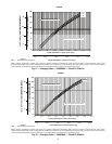
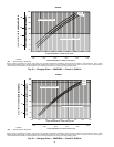
SPACE TEMPERATURE THERMISTOR (SPT) — This
sensor is a field-supplied accessory and is part of the T55 or
T56 sensor package that can be used to control space tempera-
ture on constant volume (CV) units. The sensor is connected to
the LVT. The SPT has a 10 k input channel and has a differ-
ent set of temperature vs. resistance and voltage drop perfor-
mance than the 5 k thermistors.
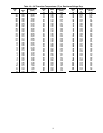
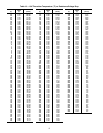
SUPPLY AIR THERMISTOR (SAT) — This sensor is field
supplied and is used to measure the supply air temperature of
the unit. The SAT thermistor is configurable to be either a 5 k
or 10 k thermistor. Care should be taken to ensure the config-
uration matches the type of thermistor which is installed. This
is configured under the Configuration menu OPT1, SAT.T and
by selecting 0 for 5 k or 1 for 10 k or 2 for none. The proper
temperature vs. resistance and voltage drop performance tables
should be followed based on the configuration.
RETURN AIR OR EVAPORATOR AIR THERMISTOR
(RAT) — This sensor is field supplied and should be located
directly upstream of the evaporator. The RAT is used to mea-
sure the evaporator entering or return air temperature of the
unit. The RAT thermistor is configurable to be either a 5 k
or 10 k thermistor. Care should be taken to ensure the
configuration matches the type of thermistor which is installed.
This is configured under the Configuration menu OPT1,
RAT.T and by selecting 0 for 5 k or 1 for 10 k or 2 for none.
The proper temperature vs. resistance and voltage drop perfor-
mance tables should be followed based on configuration.
See Table 3 for thermistor pin connection points.
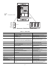
THERMISTOR/TEMPERATURE SENSOR CHECK — A
high quality digital volt-ohmmeter is required to perform this
check.
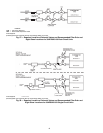
1. Connect the digital voltmeter across the appropriate the-
mistor terminals at the J8 terminal strip on the main base
board (see Fig. 61).
2. Using the voltage reading obtained, read the sensor tem-
perature from Tables 17-21.
3. To check thermistor accuracy, measure temperature at
probe location with an accurate thermocouple-type tem-
perature measuring instrument. Insulate thermocouple to
avoid ambient temperatures from influencing reading.
Temperature measured by thermocouple and temperature
determined from thermistor voltage reading should be
close, ± 5° F (3° C) if care was taken in applying thermo-
couple and taking readings.
If a more accurate check is required, unit must be shut down
and thermistor removed and checked at a known temperature
(freezing point or boiling point of water) using either voltage
drop measured across thermistor at the J8 terminal, by deter-
mining the resistance with unit shut down and thermistor
disconnected from J8. Compare the values determined with the
value read by the control in the Temperatures mode using the
scrolling marquee display.
REPLACING RETURN GAS THERMISTORS
(RGTA,B) — Add a small amount of thermal conductive
grease to the thermistor well and end of probe. Tighten the re-
taining nut
1
/
4
turn past finger tight.
WARNING
ELECTRIC SHOCK HAZARD: Turn off all power to unit
before servicing. The ENABLE/OFF/REMOTE CON-
TACT switch on control panel does not shut off control
power; use field disconnect. Failure to do so could result in
personal injury.