


21
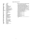
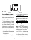
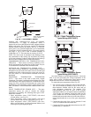
SUPPLY AIR TEMPERATURE (SAT) ACCESSORY
(33ZCSENSAT) — A supply air temperature sensor is
required for unit sizes 040-100 and all units equipped with the
digital scroll option. The SAT sensor consists of a thermistor
encased within a stainless steel probe. See Fig. 22. The SAT
sensor probe is 6 in. nominal length with 114 in. of unshielded,
2-conductor 18 AWG twisted-pair cables. The sensor tempera-
ture range is –40 to 245 F with a nominal resistance of
10,000 ohms at 77 F. The sensor has an accuracy of ±0.36 F.
NOTE: The sensor must be mounted in the discharge of the
unit, downstream of the cooling coil and before any heating
coil or heat exchanger if reheat is utilized. Be sure the probe tip
does not come in contact with any of the unit surfaces.
COMPRESSOR RETURN GAS TEMPERATURE SEN-
SOR (RGT) — These sensors are factory installed in a fric-
tion fit well located in the suction line of each circuit. They are
a 5 k thermistor connected to the main base board.
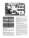
OUTDOOR-AIR TEMPERATURE SENSOR (OAT) —
This sensor is factory installed on a bracket which is inserted
through the base pan of the unit on the unit sizes 025-060 and
mounted to the back of the control box on the unit sizes 070-
100. This sensor is a 5 k thermistor connected to the main
base board.
DISCHARGE TEMPERATURE THERMISTOR
(DTT) — This sensor is only used on units with a digital
compressor. The sensor is mounted on the discharge line close
to the discharge of the digital compressor. It attaches to the dis-
charge line using a spring clip and protects the system from
high discharge gas temperature when the digital compressor is
used. This sensor is a 86 k thermistor connected to the AUX
board.
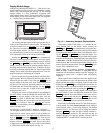
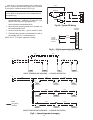
SPACE TEMPERATURE SENSOR (SPT) — The space
temperature sensors are used to measure the interior
temperature of a building. The following three types of SPT
sensors are available:
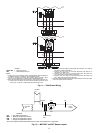
• Space temperature sensor (33ZCT55SPT) with timed
override button (see Fig. 23)
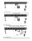
• Space temperature sensor (33ZCT56SPT) with timed
override button and set point adjustment (see Fig. 24)
• Space temperature sensor (33ZCT59SPT) with occu-
pancy override button, set point adjustment slidebar, and
LCD (liquid crystal display) display
The sensor should be mounted approximately 5 ft from the
floor in an area representing the average temperature in the
space. Allow at least 4 ft between the sensor and any corner.
Mount the sensor at least 2 ft from an open doorway.
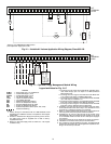
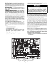
To connect the space temperature sensor (Fig. 25):
1. Use a 20 gage wire to connect the sensor to the controller.
The wire is suitable for distances of up to 500 ft. Use a
three-conductor shielded cable for the sensor and set
point adjustment connections. The standard CCN
communication cable may be used. If the set point
adjustment (slidebar) is not required, then an unshielded,
18 or 20 gage, two-conductor, twisted pair cable may be
used. Connect one wire of the twisted pair to one SEN
terminal and connect the other wire to the other SEN ter-
minal located under the cover of the space temperature
sensor.
2. Connect the other ends of the wires to terminals 21 and
22 on LVT located in the unit control box.
3. Connect the T56 set point adjustment between the SET
terminal and LVT terminal 23.
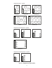
Fig. 22 — 33ZCSENSAT Sensor
.39
.08
FOAM GASKET
.40'' O.D.
.250 ±.01 Dia
5.5 ±.5
PLENUM RATED CABLE
114'' ±6
3.00
3.90
.175 DIA
x .600
NOTE: All dimensions
shown in inches.
2
3
45
61
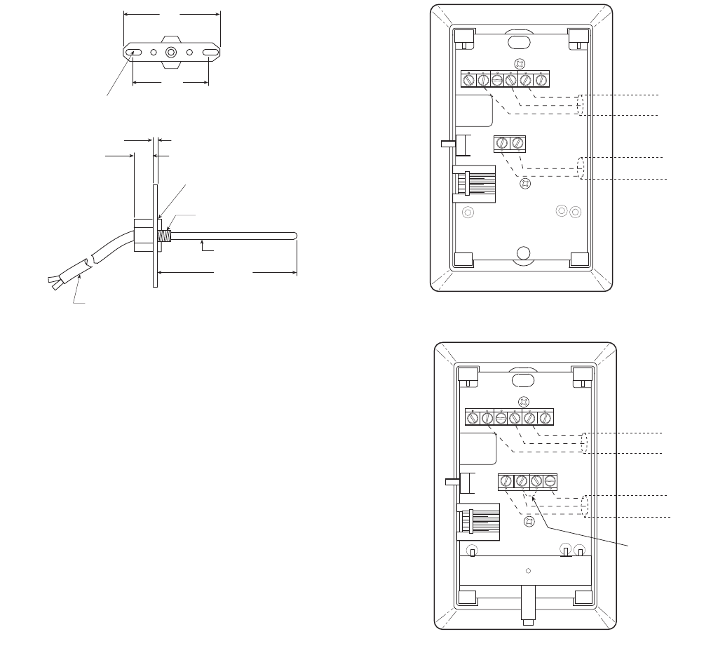
SW1
SEN
BRN (GND)
BLU (SPT)
RED(+)
WHT(GND)
BLK(-)
CCN COM
SENSOR WIRING
Fig. 23 — Space Temperature Sensor
Typical Wiring (33ZCT55SPT)
2
3
45
61
SW1
SEN
SET
Cool Warm
BRN (GND)
BLU (SPT)
RED(+)
WHT(GND)
BLK(-)
CCN COM
SENSOR WIRING
JUMPER
TERMINALS
AS SHOWN
BLK
(T56)
Fig. 24 — Space Temperature Sensor
Typical Wiring (33ZCT56SPT)