


32
DEMAND LIMIT (CCN Loadshed Controlled) — To con-
figure Demand Limit for CCN Loadshed control, set the De-
mand Limit Select (Configuration RSET DMDC) to 3.
Then configure the Loadshed Group Number (Configura-
tion RSET SHNM), Loadshed Demand Delta (Configu-
ration RSET SHDL), and Maximum Loadshed Time
(Configuration RSET SHTM). See Table 13.
The Loadshed Group number is established by the CCN
system designer. The ComfortLink controls will respond to a
Redline command from the Loadshed control. When the Red-
line command is received, the current stage of capacity is set to
the maximum stages available. Should the loadshed control
send a Loadshed command, the ComfortLink controls will re-
duce the current stages by the value entered for Loadshed De-
mand delta. The maximum loadshed time is the maximum
length of time that a loadshed condition is allowed to exist. The
control will disable the Redline/Loadshed command if no Can-
cel command has been received within the configured maxi-
mum loadshed time limit.
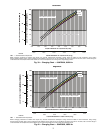
Cooling Set Point (4 to 20 mA) — A field supplied
and generated, externally powered 4 to 20 mA signal can be
used to provide the leaving temperature set point. The energy
management module (EMM) must be used for cooling set
point control using a 4 to 20 mA signal. To use the 4 to 20 mA
set point, the unit type must be configured for control type VAV
set point (Configuration OPT2 C.TYP = 9). Once config-
ured, the control will translate the input linearly with 4 mA
equal to 40 F set point and 20 mA equal to 80 F set point. Con-
nect the signal to LVT strip terminal 10,8 (+,-). See Table 14
for instructions to enable the function. Figure 34 shows how
the 4 to 20 mA signal is linearly calculated.
Digital Scroll Option — The 38AP units have a
factory-installed option for a digital scroll compressor which
provides additional stages of unloading for the unit. The digital
compressor is always installed in the A1 compressor location.
When a digital compressor is installed, a digital unloader sole-
noid (DUS) is used on the digital compressor.
DIGITAL SCROLL OPERATION — A digital scroll oper-
ates in two stages - the "loaded state" when the solenoid valve
is normally closed and the "unloaded state" when the solenoid
valve is open. During the loaded state, the compressor operates
like a standard scroll and delivers full capacity and mass flow.
However, during the unloaded state, there is no capacity
and no mass flow through the compressor. The capacity of the
system is varied by varying the time the compressor operates
in an unloaded and loaded state during a 15-second period. If
the DUS is energized for 7.5 seconds, the compressor will be
operating at 50% capacity. If the DUS is energized for 11 sec-
onds, the compressor will be operating at approximately 25%
of its capacity. Capacity is the time averaged summation of
loaded and unloaded states, and its range is continuous from
10% to 100%. Regardless of capacity, the compressor always
rotates with constant speed. As the compressor transitions from
a loaded to unloaded state, the discharge and suction pressures
will fluctuate and the compressor sound will change.
The ComfortLink controller controls and integrates the op-
eration of the DUS into the compressor staging routine to
maintain temperature control. When a digital compressor is in-
stalled, an additional discharge gas thermistor (DTT) is in-
stalled along with the AUX board for control of the DUS.
DIGITAL COMPRESSOR CONFIGURATION — When a
digital compressor is installed, the configuration parameter
Configuration Unit A1.TY is configured to YES. There is
also a maximum unload time configuration, Configuration
Unit MAX.T, that is set to 7 seconds, which indicates the
maximum unloading for the digital compressor is 50%. This is
done to optimize efficiency of the system.
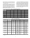
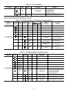
Table 14 — Configuration VAV 4 to 20 mA Set Point
MODE
(RED LED)
KEYPAD
ENTRY
SUB-MODE
KEYPAD
ENTRY
ITEM DISPLAY ITEM EXPANSION COMMENT
CONFIGURATION
DISP
UNIT
CCN
OPT1
OPT2 C.TYP 4 Unit Options 2 Controls
C.TYP 9 Machine Control Type
1 = VAV
3 = Tstat Multi
4 = Tstat 2 Stage
5 = SPT Multi
7 = PCT CAP
8 = Dual Stat
9 = VAV Set Point
ENTER
ENTER
ENTER
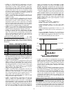
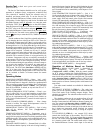
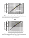
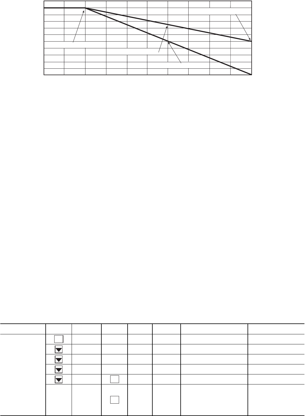
50% CAPACITY AT 20 mA
0
2
4
6
8
10
12
14
16 18
20
100
80
60
40
20
0
MAX.
ALLO
W
ABLE LO
AD (%
)
100% CAPACITY AT 4mA
75% CAPACITY AT 12 mA
50% CAPACITY AT 12 mA
DM20 = 50
DM20 = 0
DEMAND LIMIT SIGNAL – 4 - 20 mA INPUT
Fig. 33 — 4 to 20 mA Demand Limiting — Demand Limit Select (DMDC = 2)