


19
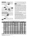
Table 3 — Thermistor Designations
Table 4 — Switch Inputs
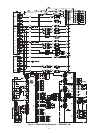
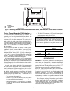
Compressor Expansion Module (CXB) — The
CXB is only used on unit sizes 070-100 to provide additional
inputs and outputs for fans and compressors when the unit has
more than 4 compressors.
AUX Board (AUX) — The AUX is used with the digital
scroll option and the low ambient head pressure option. It pro-
vides additional inputs and outputs for digital scroll control
along with analog outputs to control head pressure control fan
speeds.
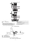
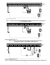
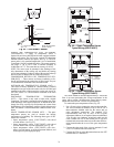
Enable/Off/Remote Contact Switch — The Enable/
Off/Remote Contact switch is a 3-position switch used to
control the unit. When switched to the Enable position, the unit
is under its own control. Move the switch to the Off position to
shut the unit down. Move the switch to the Remote Contact po-
sition and a field-installed dry contact can be used to start the
unit. The contacts must be capable of handling a 24 vac, 50 mA
load. In the Enable and Remote Contact (dry contacts closed)
positions, the unit is allowed to operate and respond to the
scheduling configuration, CCN configuration and set point
data. See Fig. 21.
Emergency On/Off Switch — The Emergency On/Off
switch should only be used when it is required to shut the
unit off immediately. Power to the MBB, CXB, AUX, EMM,
and scrolling marquee display is interrupted when this switch is
off and all outputs from these modules will be turned off.
Board Addresses — The main base board (MBB) has a
3-position Instance jumper that must be set to ‘1.’ All other
boards have 4-position DIP switches. All switches are set to
‘On’ for all boards.
Control Module Communication
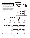
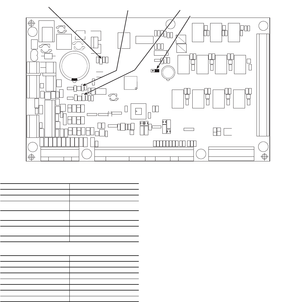
RED LED — Proper operation of the control boards can be
visually checked by looking at the red status LEDs
(light-emitting diodes). When operating correctly, the red status
LEDs should be blinking in unison at a rate of once every
2 seconds. If the red LEDs are not blinking in unison, verify
that correct power is being supplied to all modules. Be sure that
the main base board (MBB) is supplied with the current soft-
ware. If necessary, reload current software. If the problem still
persists, replace the MBB. A red LED that is lit continuously or
blinking at a rate of once per second or faster indicates that the
board should be replaced.
GREEN LED — The MBB has one green LED. The Local
Equipment Network (LEN) LED should always be blinking
whenever power is on. All other boards have a LEN LED
which should be blinking whenever power is on. Check LEN
connections for potential communication errors at the board J3
and/or J4 connectors. Communication between modules is
accomplished by a 3-wire sensor bus. These 3 wires run in
parallel from module to module. The J4 connector on the MBB
provides both power and communication directly to the
marquee display only.
YELLOW LED — The MBB has one yellow LED. The
Carrier Comfort Network (CCN) LED will blink during times
of network communication.
THERMISTOR INPUT PIN CONNECTION POINT
Return Air (Accessory) MBB J8-11,12; LVT 19,20
Supply Air (Accessory) MBB J8-12,13; LVT 11,19
Compressor Return Gas
Temperature A
MBB J8-1,2
Compressor Return Gas
Temperature B
MBB J8-3,4
Outdoor Air Temperature MBB J8-7,8
Discharge Temperature
(Digital Option Only)
AUX J6-1,2
Space Temperature (Accessory) MBB J8-5,6; LVT 21,22
SWITCH INPUT PIN CONNECTION POINT
Thermostat Y1 (Accessory) LVT 12,18
Thermostat Y2 (Accessory) LVT 15,18
Fan Status 1 (Accessory) LVT 16,18
Fan Status 2 (Accessory) LVT 17,18
Remote On/Off LVT 13,14
High Pressure Switch A MBB J6-4
High Pressure Switch B MBB J6-6
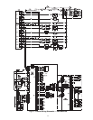
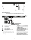
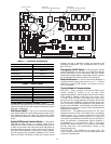
CEPL130346-01
STATUS
LEN
J1
J2
J4
J3
J5
J6
J7
J8
J9
J10
CCN
RED LED - STATUS GREEN LED -
LEN (LOCAL EQUIPMENT NETWORK)
YELLOW LED -
CCN (CARRIER COMFORT NETWORK)
INSTANCE JUMPER
K11
K10 K9
K8
K7
K6
K5
K4
K3 K2
K1
Fig. 20 — Main Base Board