


22
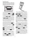
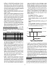
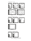
Units on the CCN can be monitored from the space using
the RJ11 connector provided with the space sensor, if desired.
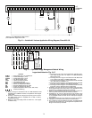
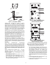
To wire the RJ11 connector into the CCN (Fig. 26):
1. Cut the CCN wire and strip ends of the red (+), white
(ground), and black (–) conductors. (If another wire color
scheme is used, strip ends of appropriate wires.)
2. Insert and secure the red (+) wire to terminal 5 of the
space temperature sensor terminal block.
3. Insert and secure the white (ground) wire to terminal 4 of
the space temperature sensor.
4. Insert and secure the black (–) wire to terminal 2 of the
space temperature sensor.
5. Connect the other end of the communication bus cable to
the remainder of the CCN communication bus.
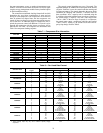
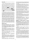
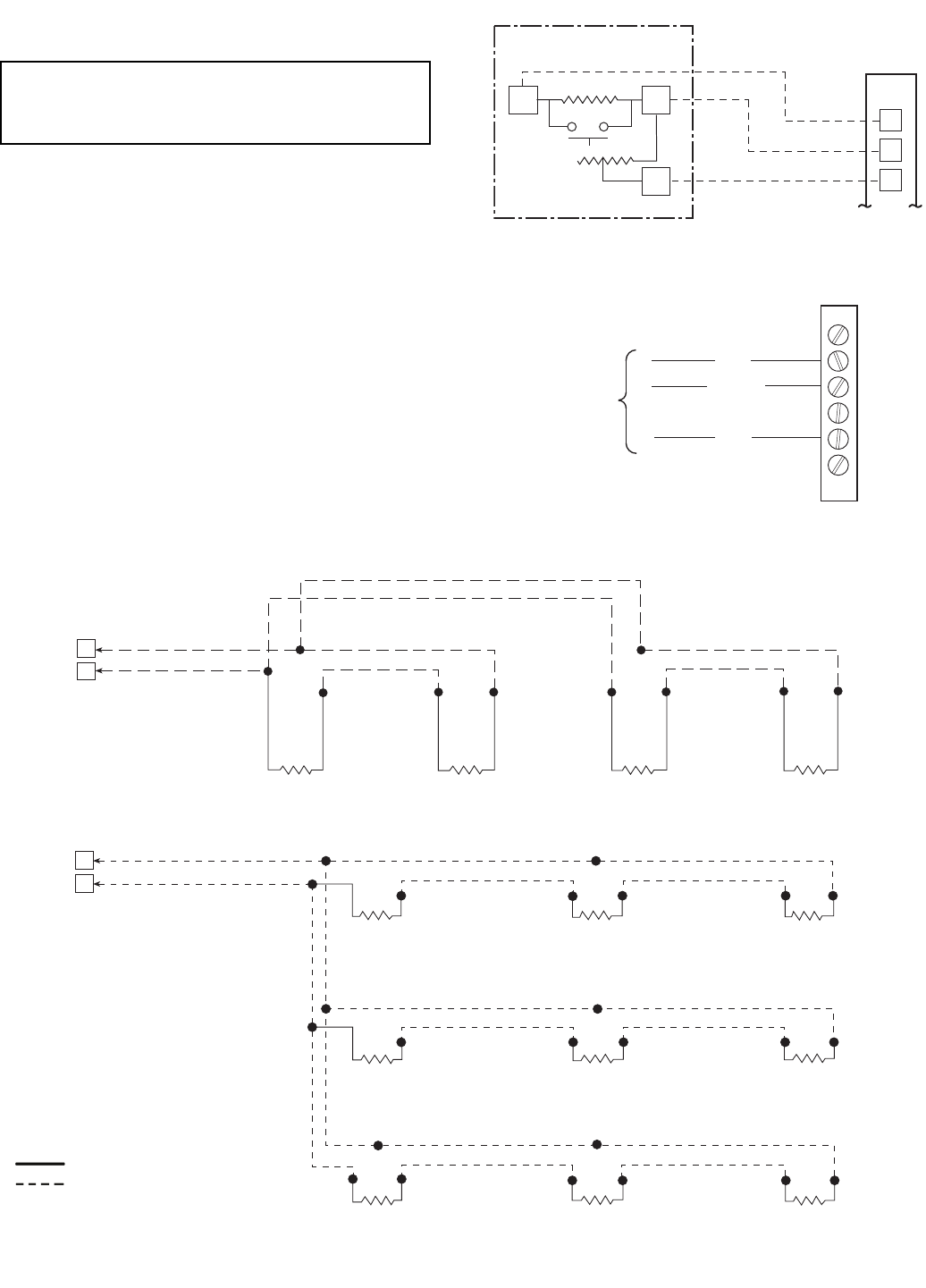
NOTE: See Fig. 27 for space temperature averaging.
IMPORTANT: The cable selected for the RJ11 connector
wiring MUST be identical to the CCN communication bus
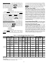
wire used for the entire network. Refer to Table 5 for
acceptable wiring.
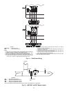
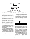
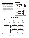
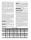
SPT
SENSOR
SEN
SEN
SET
LVT
21
22
23
Fig. 25 — Typical SPT Wiring
T-55 SPACE
SENSOR
CCN+
CCN GND
CCN-
TO CCN
COMM 1
BUS (PLUG)
AT UNIT
1
2
3
4
5
6
Fig. 26 — CCN Communications Bus Wiring to
Optimal Space Sensor RJ11 Connector
J6
6
7
RED
BLK
RED
RED
BLK
BLK
BLK
RED
BLK
RED
SENSOR 1 SENSOR 2 SENSOR 3 SENSOR 4
J6
6
7
RED
BLK
RED
BLK
SENSOR 2
SENSOR 1
RED
RED
BLK
SENSOR 3
SENSOR 4
BLK
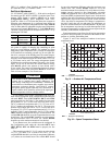
BLK
RED
RED
RED
BLK
BLK
SENSOR 8
SENSOR 9
SENSOR 5
RED
BLK
SENSOR 6
SENSOR 7
BLK
RED
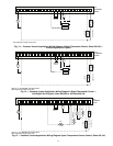
SPACE TEMPERATURE AVERAGING — 4 SENSOR APPLICATION
Fig. 27 — Space Temperature Averaging
LEGEND
Factory Wiring
Field Wiring
SPACE TEMPERATURE AVERAGING — 9 SENSOR APPLICATION