


2
When working on this equipment, observe precautions in
the literature, and on tags, stickers, and labels attached to the
equipment, and any other safety precautions that apply. Follow
all safety codes. Wear safety glasses and work gloves. Use
care in handling, rigging, and setting this equipment, and in
handling all electrical components.
GENERAL
This publication contains Controls Start-Up, Service,
Operation, and Troubleshooting information for the Gemini™
Select 38AP condensing units with ComfortLink controls. See
Table 1 for unit size information.
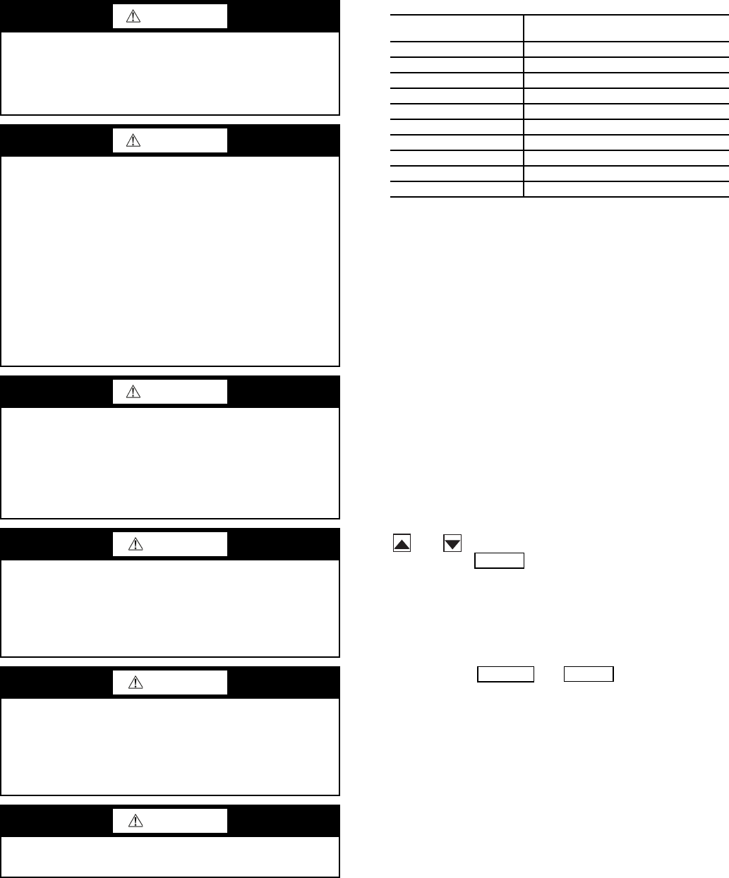
Table 1 — Unit Sizes
CONTROLS
General —
The 38AP air-cooled condensing unit contains
the ComfortLink™ electronic control system that controls and
monitors all operations of the unit.
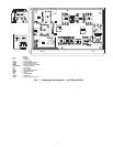
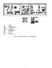
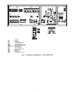
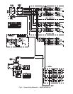
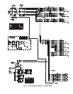
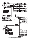
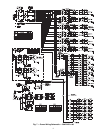
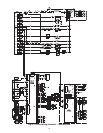
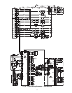
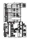
The control system is composed of several components as
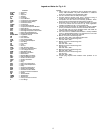
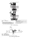
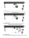
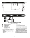
listed in the sections below. See Fig. 1-3 for typical control box
drawing. See Fig. 4-17 for power and control wiring.
Conventions Used in This Manual — The follow-
ing conventions for discussing configuration points for the
local display (scrolling marquee or Navigator™ accessory)
will be used in this manual.
Point names will be written with the mode name first, then
any sub-modes, then the point name, each separated by an
arrow symbol (. Names will also be shown in bold
and italics. As an example, the Lead/Lag Circuit Select Point,
which is located in the Configuration mode, Option sub-mode,
would be written as Configuration OPT2LLCS.
This path name will show the user how to navigate through
the local display to reach the desired configuration. The user
would scroll through the modes and sub-modes using the
and keys. The arrow symbol in the path name repre-
sents pressing to move into the next level of the
menu structure.
When a value is included as part of the path name, it will be
shown at the end of the path name after an equals sign. If the
value represents a configuration setting, an explanation will
be shown in parenthesis after the value. As an example,
ConfigurationOPT2LLCS = 2 (Circuit A leads).
Pressing the and keys simultaneously
will scroll an expanded text description of the point name or
value across the display. The expanded description is shown in
the local display tables but will not be shown with the path
names in text.
The CCN (Carrier Comfort Network
®
) point names are also
referenced in the local display tables for users configuring the
unit with CCN software instead of the local display. The CCN
tables are located in Appendix B of the manual.
WARNING
Electrical shock can cause personal injury and death. Shut
off all power to this equipment during installation and
service. There may be more than one disconnect switch.
Tag all disconnect locations to alert others not to restore
power until work is completed.
WARNING
DO NOT VENT refrigerant relief valves within a building.
Outlet from relief valves must be vented outdoors in
accordance with the latest edition of ANSI/ASHRAE
(American National Standards Institute/American Society
of Heating, Refrigeration and Air Conditioning Engineers)
15 (Safety Code for Mechanical Refrigeration). The
accumulation of refrigerant in an enclosed space can
displace oxygen and cause asphyxiation. Provide adequate
ventilation in enclosed or low overhead areas. Inhalation of
high concentrations of vapor is harmful and may cause
heart irregularities, unconsciousness or death. Misuse can
be fatal. Vapor is heavier than air and reduces the amount
of oxygen available for breathing. Product causes eye and
skin irritation. Decomposition products are hazardous.
WARNING
DO NOT attempt to unbraze factory joints when servicing
this equipment. Compressor oil is flammable and there is
no way to detect how much oil may be in any of the
refrigerant lines. Cut lines with a tubing cutter as required
when performing service. Use a pan to catch any oil that
may come out of the lines and as a gage for how much oil
to add to system. DO NOT re-use compressor oil.
CAUTION
This unit uses a microprocessor-based electronic control
system. Do not use jumpers or other tools to short out
components, or to bypass or otherwise depart from recom-
mended procedures. Any short-to-ground of the control
board or accompanying wiring may destroy the electronic
modules or electrical components.
CAUTION
Puron
®
refrigerant (R-410A) systems operate at higher
pressures than standard R-22 systems. Do not use R-22 ser-
vice equipment or components on Puron refrigerant equip-
ment. If service equipment is not rated for Puron
refrigerant, equipment damage or personal injury may
result.
CAUTION
Refrigerant charge must be removed slowly to prevent loss
of compressor oil that could result in compressor failure.
38AP UNIT SIZE
NOMINAL CAPACITY,
TONS, 60 Hz
025 25
027 27
030 30
040 40
050 50
060 60
070 70
080 80
090 90
100 100
ENTER
ESCAPE
ENTER