29
CHIL_S_S variable is 'Stop.' Similarly, the control mode will
be 6 when the CHIL_S_S variable is 'Start.'
Set Point Adjustment
CV SET POINT ADJUSTMENT — If the unit is configured
for control type SPT MULTI (C.TYP =5) and the Space Tem-
perature Offset Sensor is enabled. (SP.O.S) set to enable
[Configuration OPT1]. Space temperature offset corre-
sponds to a slider on a T56 sensor that allows the occupant to
adjust the space temperature by a configured range during an
occupied period. The space temperature offset range (SP.O.R)
value is either added or subtracted from the space temperature
cool set point. Example SPS.P equals 72 F and SP.O.R equals
5 then the cooling set point can be adjusted from 68 to 77 F by
adjusting the T56 slider.
VAV SUPPLY AIR TEMPERATURE RESET — The con-
trol system is capable of changing the controlling set point
based on several different methods. The methods are return
temperature, space temperature (SPT), outside air temperature
(OAT) and from an externally powered 4 to 20 mA signal. Re-
turn air is a measure of the building load. The return tempera-
ture reset is in effect an average building load reset method. An
accessory sensor must be used for SPT reset; either a T55, T56,
or T59 sensor can be used. The energy management module
(EMM) must be used for temperature reset using a 4 to 20 mA
signal. To use 4 to 20 mA reset, one variable must be config-
ured MA.DG, which is the amount of reset desired with a
20 mA signal. The control will interpolate between 0 degrees
reset at 4 mA and the value entered for MA.DG at 20 mA. See
Table 10 for an example of 4 to 20 mA reset.
To use Outdoor Air or Space Temperature reset, four vari-
ables must be configured. In the Configuration mode under the
sub-mode RSET, items CRST, RM.NO, RM.F and RT.DG
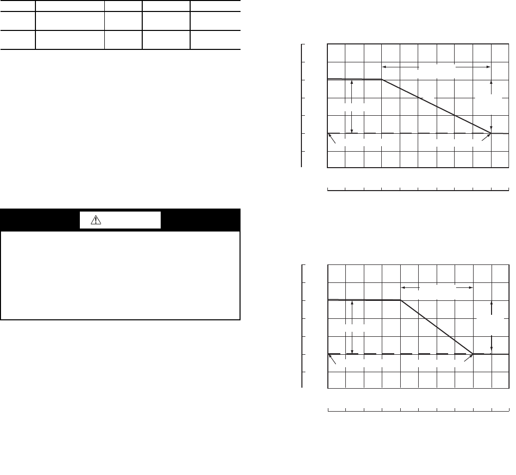
must be properly set. See Table 11. The outdoor air reset exam-
ple provides 0° F (0° C) reset to the active set point at 85 F
(29.4 C) outdoor-air temperature and 6 F (3.3 C) reset at 55 F
(12.8 C) outdoor-air temperature. See Fig 31. The space tem-
perature reset example provides 0° F (0° C) reset to the active
set point at 72 F (22.2 C) space temperature and 6 F (3.3 C) re-
set at 68 F (20.0 C) space temperature. See Fig 32. The variable
CRST should be configured for the type of reset desired. The
variable RM.NO should be set to the temperature that no reset
should occur. The variable RM.F should be set to the tempera-
ture that maximum reset is to occur. The variable RM.DG
should be set to the maximum amount of reset desired.
To use Return reset, four variables must be configured. In
the Configuration mode under the sub-mode RSET, items
CRST, RT.NO, RT.F and RT.DG must be properly set. See
Table 12.
This example provides 5 F (2.8 C) active set point reset at
2 F (1.1 C) T and 0° F (0° C) reset at 10 F (5.6 C) T. The
variable RT.NO should be set to the air temperature difference
( T) where no reset should occur. The variable RT.F should
be set to the temperature difference where the maximum reset
should occur. The variable RM.DG
should be set to the
maximum amount of reset desired. To verify that reset is func-
tioning correctly proceed to Run Status mode, sub-mode
VIEW, and subtract the active set point (SETP) from the con-
trol point (CTPT) to determine the degrees reset. Under normal
operation, the unit will maintain a constant leaving temperature
approximately equal to the cooling set point. As the unit load
varies, the return air temperature will change in proportion to
the load. Usually the unit size and supply air temperature set
point are selected based on a full-load condition. At part load,
the air temperature set point may be colder than required. If the
leaving air temperature was allowed to increase at part load, the
efficiency of the machine would increase.
Return temperature reset allows for the leaving temperature
set point to be reset upward as a function of the return air tem-
perature or, in effect, the building load.
Figures 31 and 32 are examples of outdoor air and space
temperature reset.
ITEM EXPANSION RANGE UNITS CCN POINT
SP.O.S
Space Temp
Offset Sensor
Enable/
Disable
SPTOSENS
SP.O.R
Space Temp
Offset Range
1-10 SPTO_RNG
CAUTION
Care should be taken when interfacing with other control
systems due to possible power supply differences; full
wave bridge versus half wave rectification. Connection of
control devices with different power supplies may result in
permanent equipment damage. ComfortLink™ controls
incorporate power supplies with half wave rectification. A
signal isolation device should be utilized if the signal gen-
erator incorporates a full wave bridge rectifier.
64
62
60
58
56
54
52
17.8
16.7
15.6
14.4
13.3
12.2
11.1
40 45 50 55 60 65 70 75 80 85 90
4.4 7.2 10.0 12.8 15.6 18.3 21.1 23.9 26.7 29.4 32.2
OUTSIDE TEMPERATURE (F)
OUTSIDE TEMPERATURE (C)
SAT TEMPERATURE (F)
MAXIMUM RESET
RESET SET POINT
CHILLED SET POINT
CHANGE
IN SAT
SET POINT
CHANGE IN
RESET TEMPERATURE
SAT
SAT TEMPERATURE (C)
64
62
60
58
56
54
52
17.8
16.7
15.6
14.4
13.3
12.2
11.1
65 66 67 68 69 70 71 72 73 74
18.3 18.9 19.4 20.0 20.6 21.1 21.7 22.2 22.8 23.3
SPACE TEMPERATURE (F)
SPACE TEMPERATURE (C)
SAT TEMPERATURE (F)
MAXIMUM RESET
SAT
RESET SET POINTCHILLED SET POINT
CHANGE IN
RESET TEMPERATURE
CHANGE
IN SAT
SET POINT
SAT TEMPERATURE (C)
LEGEND
Fig. 31 — Outdoor-Air Temperature Reset
SAT — Supply Air Temperature
LEGEND
Fig. 32 — Space Temperature Reset
SAT — Supply Air Temperature


