


25
the return temperature, space, or outdoor-air temperature reset
features. It can also be reset from an external 4 to 20 mA signal
(requires energy management module factory-installed option
or field-installed accessory).
The control has an automatic lead-lag feature built in which
determines the wear factor (combination of starts and run
hours) for each compressor. If all compressors are off and less
than 30 minutes has elapsed since the last compressor was
turned off, the wear factor is used to determine which compres-
sor to start next. As additional stages of compression are re-
quired, the processor control will add them. If a circuit is to be
stopped, the compressor with the lowest wear factor will be
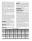
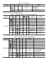
shut off first. See Table 7 for compressor size information and
Table 8 for compressor loading sequence.
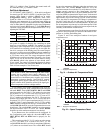
The capacity control algorithm runs every 30 seconds. The
algorithm attempts to maintain the control point at the desired
set point. Each time it runs, the control reads the entering and
leaving temperatures. The control determines the rate at which
conditions are changing and calculates 2 variables based on
these conditions. Next, a capacity ratio is calculated using the
2 variables to determine whether or not to make any changes to
the current stages of capacity. This ratio value ranges from
–100 to +100%. If the next stage of capacity is a compressor,
the control starts (stops) a compressor when the ratio reaches
+100% (-100%). A delay of 90 seconds occurs after each ca-
pacity step change. Refer to Table 8.
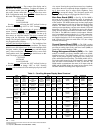
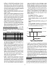
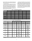
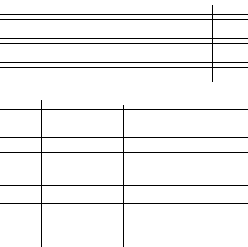
Table 7 — Compressor Size Information
Table 8 — Part Load Data Percent
NOTES:
1. These capacity steps may vary due to different capacity staging
sequences.
2. When unit is equiped with digital scroll option, sequence A is always
used.
UNIT SIZE
CIRCUIT A (Nominal hp) CIRCUIT B (Nominal hp)
Compressor A1 Compressor A2 Compressor A3 Compressor B1 Compressor B2 Compressor B3
38APS025 11 11 — — — —
38APD025 11 — — 11 — —
38APS027 13 13 — — — —
38APD027 13 — — 13 — —
38APS030 15 15 — — — —
38APD030 15 — — 15 — —
38APS040 13 13 13 — — —
38APD040 10 10 — 9 9 —
38APS050 15 15 15 — — —
38APD050 12 12 — 13 13 —
38APD060 13 13 — 15 15 —
38APD070 15 15 — 11 11 11
38APD080 15 15 — 15 15 15
38APD090 13 13 13 15 15 15
38APD100 15 15 15 15 15 15
38AP UNIT SIZE
CONTROL
STEPS
LOADING SEQUENCE A LOADING SEQUENCE B
% Displacement Compressor % Displacement Compressor
38APS025-030
150A1——
2 100 A1,A2 — —
38APD025-030
1 50A150B1
2 100 A1, B1 100 A1,B1
38APS040,050
133A1——
267A1,A2——
3 100 A1,A2,A3 — —
38APD040
127A123B1
2 50 A1,B1 50 A1,B1
3 77A1,A2,B1 73A1,B1,B2
4 100 A1,A2,B1,B2 100 A1,A2,B1,B2
38APD050,060
123A127B1
2 50 A1,B1 50 A1,B1
3 73A1,A2,B1 77A1,B1,B2
4 100 A1,A2,B1,B2 100 A1,A2,B1,B2
38APD070
115A115B1
2 42 A1,B1 42 A1,B1
3 57A1,A2,B157A1,B1,B2
4 85 A1,A2,B1,B2 85 A1,A2,B1,B2
5 100 A1,A2,B1,B2,B3 100 A1,A2,B1,B2,B3
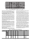
38APD080
120A120B1
2 40 A1,B1 40 A1,B1
3 60A1,A2,B160A1,B1,B2
4 80 A1,A2,B1,B2 80 A1,A2,B1,B2
5 100 A1,A2,B1,B2,B3 100 A1,A2,B1,B2,B3
38APD090
115A118B1
2 32 A1,B1 32 A1,B1
3 48A1,A2,B151A1,B1,B2
4 66 A1,A2,B1,B2 66 A1,A2,B1,B2
5 82 A1,A2,A3,B1,B2,B3 85 A1,A2,B1,B2,B3
6 100 A1,A2,A3,B1,B2,B3 100 A1,A2,A3,B1,B2,B3
38APD100
117A117B1
2 33 A1,B1 33 A1,B1
3 50A1,A2,B150A1,B1,B2
4 67 A1,A2,B1,B2 67 A1,A2,B1,B2
5 83A1,A2,A3,B1,B283A1,A2,B1,B2,B3
6 100 A1,A2,A3,B1,B2,B3 100 A1,A2,A3,B1,B2,B3