


24
• C.TYP = 3 (TSTAT-MULTI) configuration will force
the MBB to monitor the thermostat inputs to make a
determination of mode. Unlike traditional 2-stage ther-
mostat control, the unit is allowed to use multiple stages
of cooling control and perform VAV style operation. The
control will be able to call out a low set point or a high
set point to maintain supply air temperature. (Required
for 025-030 units with digital scroll option and 040-100
units with two-stage thermostat control.)
• C.TYP = 4 (TSTAT-2STG) configuration will force the
MBB to monitor the thermostat inputs to make a deter-
mination of mode.
• C.TYP = 5 (SPT-MULTI) configuration will force the
MBB to monitor a space temperature sensor to make a
determination of mode. Unlike traditional 2-stage space
temperature control, the unit is allowed to use multiple
stages of cooling control and perform VAV style opera-
tion. The control will be able to call out a low set point or
a high set point to maintain supply air temperature.
• C.TYP = 7 (% CAPACITY) configuration will force the
MBB to monitor the 4-20 cooling demand CL.MA input
and translate this into desired % capacity for the unit.
• C.TYP = 9 (VAV-SETPOINT) configuration will force
the MBB to monitor the 4-20 cooling demand CL.MA
input. This value will be translated into a desired leav-
ing-air set point ranging from 40 to 80 F. The control will
translate the input linearly with 4 ma equal to 40 F set
point and 20 mA equal to 80 F set point.
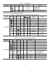
Unit Capacity Control Based on Unit Type
— The MBB
uses several set points to control capacity depending on unit
type. The set points are located in the set point area of the dis-
play SetPoints COOL. Refer to Table 6 and the following
descriptions.
Table 6 — Unit Capacity Control
• C.TYP = 1 (VAV-RAT) is a capacity control routine that
controls compressor capacity to supply air temperature.
The MBB will attempt to control leaving temperature to
the control point (CTPT) which equals CSP1 plus any
reset which is being applied.
• C.TYP = 3 (TSTAT-MULTI) configuration will force the
MBB to monitor the thermostat inputs to make a deter-
mination of control point (CTPT). The control will vary
the control point based on Y1 and Y2 inputs. When Y1 is
closed CSP1 will be used and when Y2 is closed CSP2
will be used as the supply air temperature set point.
CSP1 should be greater than CSP2.
• C.TYP = 4 (TSTAT-2STG) configuration will force the
MBB to monitor the thermostat inputs to make a deter-
mination of mode and capacity. If Y1 input is closed,
50% of the unit capacity will be energized and if Y2 is
closed, 100% of the unit capacity will be energized.
NOTE: This is not a preferred method of control for units
with greater than 2 stages of capacity
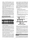
• C.TYP = 5 (SPT-MULTI) configuration will force the
MBB to monitor the thermostat inputs to determine
mode and cooling set point as the unit is controlled by
space temperature vs space temperature set point SPS.P.
Unlike traditional 2-stage thermostat control, the unit is
allowed to use multiple stages of cooling control and per-
form VAV style operation. The control will be able to call
out a low set point (CSP1) or high set point (CSP2) for
supply air depending on space temperature vs space
temperature set point. The control uses SPS.P, LC.ON,
HC.ON, and LC.OF to determine the leaving set point.
LC.ON and HC.ON are added to the space temperature
set point to determine when cooling mode will begin and
when CSP1 and CSP2 will be used for leaving set point.
Based on LC.OF, the control point transitions between
CSP1 and CSP2. LC.OF is used to calculate the space tem-
perature at which control point is raised based on space tem-
perature vs space temperature set point (SPS.P) plus
LC.ON minus LC.OF. The control point transition from
CSP2 to CSP1 occurs when space temperature is below
LC.OF divided by 2.
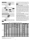
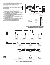
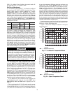
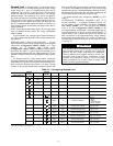
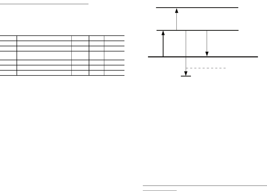
For example (see Fig. 29):
Given: SPS.P = 72 F, LC.ON = 1, HC.ON = 3,
LC.OF = 2 F, CSP1 = 60 F, and CSP2 = 55 F
If space temperature equals 73 F (72+1) (Low Cool)
cooling will begin and control set point equals 60 F
(CSP1).
If space temperature is greater than 76 F (72+1+3 = 76)
(High Cool), control point set point would equal 55 F
(CSP2).
If space temperature falls below 72 F (73-2/2) (Low
Cool minus LC.OF/2), control point transitions back to
60 F CSP1 if space continues to fall below 71 F (73-2)
(Low Cool minus LC.OF), the unit is shut off.
• C.TYP = 7 (% CAPACITY) configuration will force the
MBB to monitor the input 4-20 cooling demand CL.MA
and translate this into desired % capacity for the unit.
The control will attempt to match the desired capacity
insuring the unit operates the compressor within com-
pressor safeties and timeguards. (Requires the EMM
option or accessory.)
• C.TYP = 9 (VAV-SETPOINT) configuration will force
the MBB to operate as a VAV unit and control capacity to
meet supply air temperature. The control point is devel-
oped from the 4-20 cooling demand CL.MA input value.
The 4 to 20 mA input will be translated into a desired
control point ranging from 40 to 80 F. The control will
translate the input linearly with 4 mA equal to 40 F set
point and 20 mA equal to 80 F set point. (Requires the
EMM option or accessory.)
Capacity Control Logic when Control is Controlling to Sup-
ply Temperature — The control system cycles compressors,
hot gas bypass and the digital compressor to maintain the sup-
ply temperature at or close to the control point of the unit. The
SAT and RAT sensors are used by the main base board (MBB)
to determine the temperature drop across the evaporator and
are used in determining the optimum time to add or subtract ca-
pacity stages. The CSP set points can be automatically reset by
ITEM DESCRIPTION RANGE UNITS DEFAULT
CSP1 Cooling Set Point 1 40-80 F 65
CSP2 Cooling Set Point 2 40-80 F 55
SPS.P Space Temperature Cooling Set
Point
65-80 F 74
L.C.ON Demand Level Low Cool On –1-2 ^F 1.5
H.C.ON Demand Level (+) High Cool On 0.5-20.0 ^F 0.5
L.C.OF Demand Level (–) Low Cool Off 0.5-2 ^F 1
H.C.ON
L.C. OF/2
L.C.ON
Cooling Setpoint
L.C. OF
Lo Cool End 71 F
Hi Cool End 72 F72 F
73 F
76 F
Lo Cool Start
Hi Cool Start
Fig. 29 — Space Temperature vs.
Space Temperature Set Point
A48-7701