


26
MINUTES LEFT FOR START — This value is displayed
only in the network display tables (using Service Tool,
ComfortVIEW™ or ComfortWORKS
®
software) and
represents the amount of time to elapse before the unit will start
its initialization routine. This value can be zero without the
machine running in many situations. This can include being
unoccupied, ENABLE/OFF/REMOTE CONTACT switch in
the OFF position, CCN not allowing unit to start, Demand
Limit in effect, no call for cooling due to no load, and alarm or
alert conditions present. If the machine should be running and
none of the above are true, a minimum off time (DELY, see
below) may be in effect. The machine should start normally
once the time limit has expired.
MINUTES OFF TIME (Configuration OPT2
DELY) — This user-configurable time period is used by
the control to determine how long unit operation is delayed
after power is applied/restored to the unit. Typically, this time
period is configured when multiple machines are located on a
single site. For example, this gives the user the ability to pre-
vent all the units from restarting at once after a power failure.
A value of zero for this variable does not mean that the unit
should be running.
NOTE: If the unit has digital scroll or hot gas bypass, circuit A
is always lead.
LEAD/LAG DETERMINATION — This is a configurable
choice and is factory set to be automatic for all units. The value
can be changed to Circuit A or Circuit B leading as desired. Set
at automatic, the control will sum the current number of logged
circuit starts and one-quarter of the current operating hours for
each circuit. The circuit with the lowest sum is started first.
Changes to which circuit is the lead circuit and which is the lag
are also made when total machine capacity is at 100% or when
there is a change in the direction of capacity (increase or
decrease) and each circuit’s capacity is equal.
CAPACITY CONTROL OVERRIDES — The following over-
rides will modify the normal operation of the routine.
Deadband Multiplier
— The user configurable deadband mul-
tiplier (Configuration SLCT Z.GN) has a default value of
1.0. The range is from 1.0 to 4.0. When set to other than 1.0,
this factor is applied to the capacity Load/Unload Factor. The
larger this value is set, the longer the control will delay between
adding or removing stages of capacity.
First Stage Override
— If the current capacity stage is zero,
the control will modify the routine with a 1.2 factor on adding
the first stage to reduce cycling. This factor is also applied
when the control is attempting to remove the last stage of
capacity.
Slow Change Override
— This control prevents the capacity
stages from being changed when the supply temperature is
close to the set point (within an adjustable deadband) and mov-
ing toward the set point.
Ramp Loading
— The ramp loading control (Configuration
SLCT CRMP) limits the rate of change of supply temper-
ature. If the unit is in a Cooling mode and configured for Ramp
Loading, the control makes 2 comparisons before deciding to
change stages of capacity. The control calculates a temperature
difference between the control point and supply temperature. If
the difference is greater than 4° F (2.2° C) and the rate of
change (°F or °C per minute) is more than the configured Cool-
ing Ramp Loading value (CRMP), the control does not allow
any changes to the current stage of capacity.
Minimum Load Control
— If equipped, the minimum load
control valve is energized only when one compressor on the
circuit is running and the unit is unloading.
Low Saturated Suction Protection
— The control will try to
prevent shutting a circuit down due to low saturated suction
conditions by removing stages of capacity. See Alerts section.
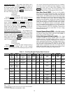
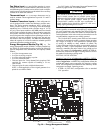
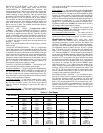
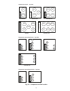
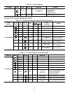
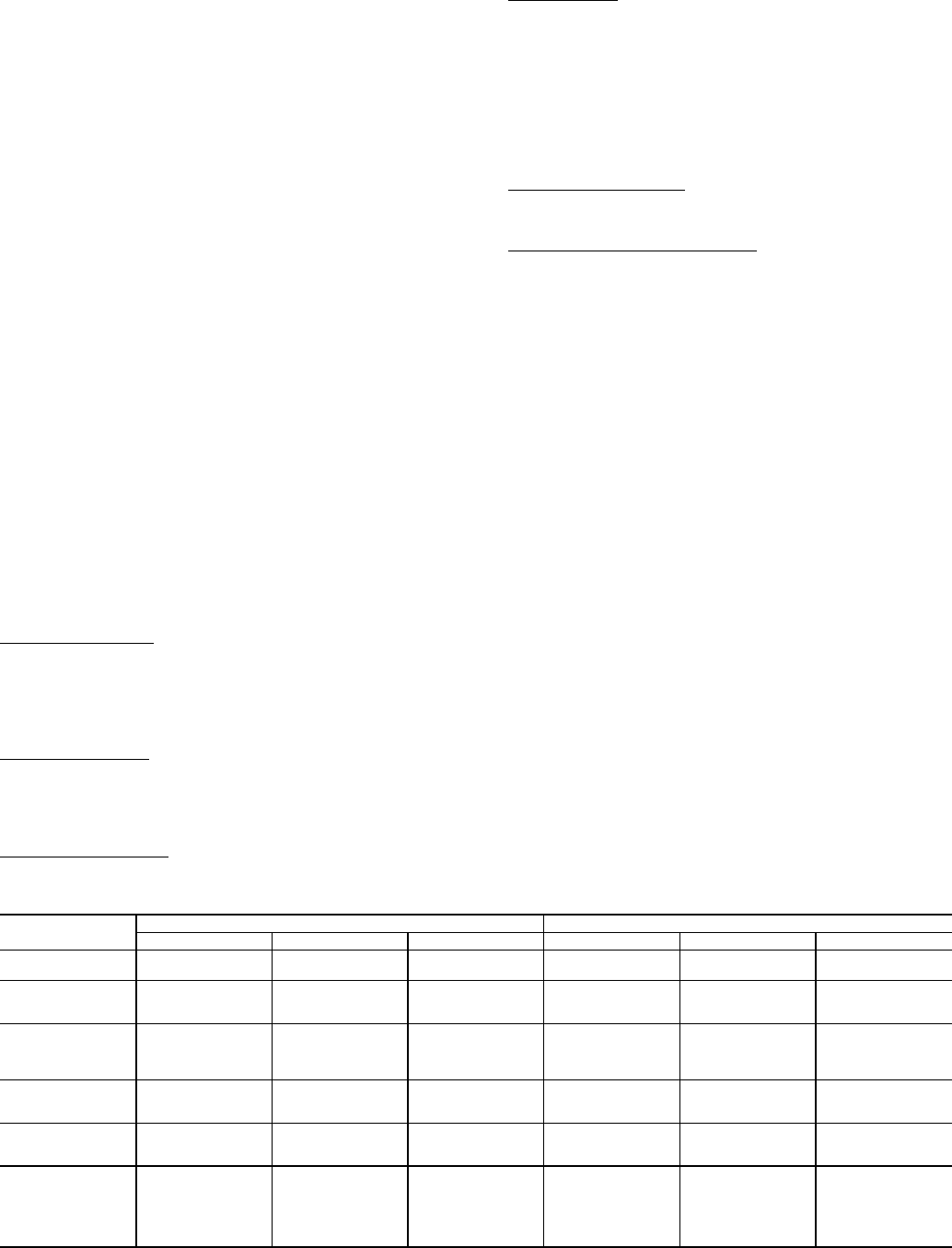
Head Pressure Control — The main base board
(MBB) controls the condenser fans to maintain the lowest
condensing temperature possible, and thus the highest unit
efficiency. The MBB uses the saturated condensing tempera-
ture input from the discharge pressure transducer and outside
air temperature sensor to control the fans. If OAT is greater
than 70 F before a circuit is starting, then all condenser fan
stages will be energized. A fan stage is increased based on
SCT. When the highest SCT of both circuits is greater than fan
on set point, then an additional stage of fan will be added to the
current fan stage. Fan On Set Point (F. ON) equals Head Set
Point ON (115 F) except after a fan stage increase when Head
Set Point is increased by Fan Stage Delta (10 F). A fan stage is
decreased when the SCTs of both circuits are less than fan off
set point for two minutes. Fan Off Set Point (F. O FF ) equals
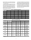
Head Set Point OFF (–72 F). Table 9 shows the number of fan
stages, contactors energized and the fans that are on during the
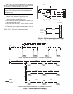
fan stage. Unit sizes 025 to 060 have common fan control. Unit
sizes 070 to 100 have some fans that are common and some
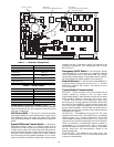
that are controlled individually. Figure 30 shows the location
of each fan and compressor within the unit.
MOTORMASTER
®
V OPTION — For low-ambient opera-
tion, the first stage of fans is equipped with the Motormaster V
head pressure controller option or accessory. For units with
common fans, the control will control the Head Pressure Set-
point (–10 F) and the highest SCT to try to maintain it at 100 F.
Unit sizes 070 to 100 have one Motormaster V for each circuit
and the control tries to maintain SCT at 100 F for the circuit.
The controller is given an ON command with the first stage of
fan and adjusts fan speed.
Table 9 — Fan Stages
* Fan Stage 1 on unit size 070 is used only when ambient temperature is less than 32 F.
38AP UNIT SIZE
CIRCUIT A STAGES/COMMON FAN STAGES CIRCUIT B FAN STAGES
Fan Stage Contactor Energized Fans Operating Fan Stage Contactor Energized Fans Operating
025-030
Stage 1
Stage 2
FC1
FC1,2
OFM1
OFM1,2
———
040,050
Stage 1
Stage 2
Stage 3
FC1
FC2
FC1,2
OFM3
OFM1,2
OFM1,2,3
———
060
Stage 1
Stage 2
Stage 3
Stage 4
FC1
FC2
FC1,2
FC1,2,3
OFM3
OFM1,2
OFM1,2,3
OFM1,2,3,4
———
070
Stage 1*
Stage 2
Stage 3
FC2,4
FC1
FC1,3
OFM1,2
OFM3
OFM3,4
Stage 1*
Stage 2
Stage 3
FC1,3
FC2
FC2,4
OFM3,4
OFM1
OFM1,2
080
Stage 1
Stage 2
FC1
FC1,3
OFM5
OFM5,6,(2)
Stage 1
Stage 2
Stage 3
FC4
FC3,4
FC2,3,4
OFM3
OFM3,2,(6)
OFM3,1,2,(6)
090,100
Stage 1
Stage 2
Stage 3
Stage 4
Stage 5
Stage 6
FC4
FC1
FC4,1
FC4,3
FC1,3
FC4,1,3
OFM3
OFM5
OFM3,5
OFM3,(2),4,6
OFM5,(2),4,6
OFM3,5,(2),4,6
Stage 1
Stage 2
Stage 3
Stage 4
Stage 5
Stage 6
FC4
FC2
FC4,2
FC4,3
FC2,3
FC4,2,3
OFM3
OFM1
OFM3,1
OFM3,2,4,(6)
OFM1,2,4,(6)
OFM3,1,2,4,(6)