


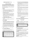

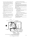
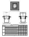
Combustion-air pipe perforated disk assembly 1
Condensate trap hole filler plug 3
Vent and combustion-air intake hole filler plug 2
CODES AND STANDARDS
Follow all national and local codes and standards in addition to
these instructions. The installation must comply with regulations
of the serving gas supplier, local building, heating, plumbing, and
other codes. In absence of local codes, the installation must
comply with the national codes listed below and all authorities
having jurisdiction in Canada.
In the United States and Canada, follow all codes and standards for
the following:
I. SAFETY
• US: National Fuel Gas Code (NFGC) NFPA 54-2002/ANSI
Z223.1-2002 and the Installation Standards, Warm Air Heating
and Air Conditioning Systems ANSI/NFPA 90B
• CANADA: National Standard of Canada, Natural Gas and
Propane Installation Code (NSCNGPIC) CSA B149.1-00
II. GENERAL INSTALLATION
• US: NFGC and the NFPA 90B. For copies, contact the National
Fire Protection Association Inc., Batterymarch Park, Quincy,
MA 02269; or for only the NFGC contact the American Gas
Association, 400 N. Capitol, N.W., Washington DC 2001
• CANADA: NSCNGPIC. For a copy, contact Standard Sales,
CSA International, 178 Rexdale Boulevard, Etobicoke (Tor-
onto), Ontario, M9W 1R3, Canada.
III. COMBUSTION AND VENTILATION AIR
• US: Section 8.3 of the NFGC, Air for Combustion and
Ventilation
• CANADA: Part 7 of the NSCNGPIC, Venting Systems and Air
Supply for Appliances
IV. DUCT SYSTEMS
• US and CANADA: Air Conditioning Contractors Association
(ACCA) Manual D, Sheet Metal and Air Conditioning Con-
tractors National Association (SMACNA), or American Soci-
ety of Heating, Refrigeration, and Air Conditioning Engineers
(ASHRAE) 2001 Fundamentals Handbook Chapter 34.
V. ACOUSTICAL LINING AND FIBROUS GLASS DUCT
• US and CANADA: current edition of SMACNA, NFPA 90B as
tested by UL Standard 181 for Class I Rigid Air Ducts
VI. GAS PIPING AND GAS PIPE PRESSURE TESTING
• US: NFGC; chapters 5, 6, 7, and 12 and national plumbing
codes
• CANADA: NSCNGPIC Parts 3, 4, 5, A, B, E, G, and H
VII. ELECTRICAL CONNECTIONS
• US: National Electrical Code (NEC) ANSI/NFPA 70-2002
• CANADA: Canadian Electrical Code CSA C22.1
ELECTROSTATIC DISCHARGE (ESD) PRECAUTIONS
CAUTION: Electrostatic discharge can affect electronic
components. Take precautions during furnace installation
and servicing to protect the furnace electronic control.
Precautions will prevent electrostatic discharges from
personnel and hand tools which are held during the
procedure. These precautions will help to avoid exposing
the control to electrostatic discharge by putting the
furnace, the control, and the person at the same electro-
static potential.
1. Disconnect all power to the furnace. Multiple disconnects
may be required. DO NOT TOUCH THE CONTROL OR
ANY WIRE CONNECTED TO THE CONTROL PRIOR
TO DISCHARGING YOUR BODY’S ELECTROSTATIC
CHARGE TO GROUND.
2. Firmly touch a clean, unpainted, metal surface of the
furnace chassis which is close to the control. Tools held in
a person’s hand during grounding will be satisfactorily
discharged.
3. After touching the chassis, you may proceed to service the
control or connecting wires as long as you do nothing that
recharges your body with static electricity (for example; DO
NOT move or shuffle your feet, DO NOT touch un-
grounded objects, etc.).
4. If you touch ungrounded objects (recharge your body with
static electricity), firmly touch furnace again before touch-
ing control or wires.
5. Use this procedure for installed and uninstalled (un-
grounded) furnaces.
6. Before removing a new control from its container, dis-
charge your body’s electrostatic charge to ground to protect
the control from damage. If the control is to be installed in
a furnace, follow items 1 through 5 before bringing the
control or yourself into contact with the furnace. Put all
used AND new controls into containers before touching
ungrounded objects.
7. An ESD service kit (available from commercial sources)
may also be used to prevent ESD damage.
INTRODUCTION
The model 355MAV 4-way multipoise, Gas-Fired, Category IV,
direct-vent condensing furnace is available in model sizes ranging
in input capacities of 40,000 to 120,000 Btuh.
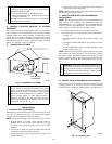
APPLICATIONS
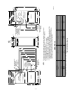
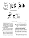
I. GENERAL
Some assembly and modifications are required for furnaces
installed in any of the 4 applications shown in Fig. 1. All drain and
pressure tubes are connected as shown in Fig. 7. See appropriate
application instructions for these procedures.
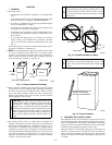
CAUTION: Local codes may require a drain pan under
entire furnace and condensate trap when a condensing
furnace is used in an attic application or over a finished
ceiling.
NOTE: In Canada, installations shall be in accordance with
current NSCNGPIC and/or local codes.
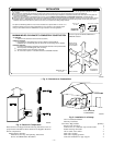
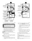
II. UPFLOW APPLICATIONS
An upflow furnace application is where furnace blower is located
below combustion and controls section of furnace, and conditioned
air is discharged upwards.
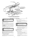
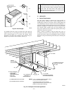
A. Condensate Trap Location (Factory-Shipped
Orientation)
The condensate trap is factory installed in the blower shelf and
factory connected for UPFLOW applications. A factory-supplied
tube is used to extend the condensate trap drain connection to the
desired furnace side for field drain attachment. See Condensate
Trap Tubing (Factory-Shipped Orientation) section for drain tube
extension details. (See Fig. 6.)
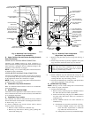
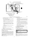
B. Condensate Trap Tubing (Factory-Shipped
Orientation)
NOTE: See Fig. 7 or tube routing label on main furnace door to
confirm location of these tubes.
—5—
→
→
→
→
→