


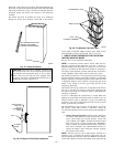
12. Support combustion-air and vent piping a minimum of
every 5 ft (3 ft for SDR-21 or -26 PVC) using perforated
metal hanging strap.
13. Slope combustion-air and vent pipes downward toward
furnace a minimum of 1/4 in. per linear ft with no sags
between hangers.
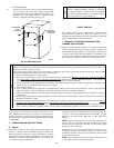
14. Use appropriate methods to seal openings where vent and
combustion-air pipes pass through roof or sidewall.
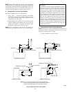
III. CONCENTRIC VENT AND COMBUSTION-AIR
TERMINATION KIT INSTALLATION
NOTE: If these instructions differ from those packaged with
termination kit, follow kit instructions.
Combustion-air and vent pipes must terminate outside structure. A
factory accessory termination kit must be installed in 1 of the
installations shown in Fig. 37, 38, 39, 40, or 41. Four termination
kits are available.
1. The 2-in. termination bracket kit is for 1-in., 1-1/2 in., and
2-in. diameter 2-pipe termination systems.
2. The 3-in. termination bracket kit is for 2-1/2 in. and 3-in.
diameter 2-pipe termination systems.
3. The 2-in. concentric vent/air termination kit is for 1-in.,
1-1/2 in., 2-in., and 2-1/2 in. diameter pipe systems when
single penetration of wall or roof is desired.
4. The 3-in. concentric vent/air termination kit is for 2-1/2 in.
and 3-in. diameter pipe systems when single penetration of
wall or roof is desired.
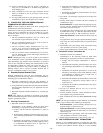
NOTE: Shaded parts in Fig. 37, 38, 39, 40, and 41 are considered
to be terminations. These components should NOT be counted
when determining pipe diameter. Roof termination is preferred
since it is less susceptible to damage, has reduced chances to take
in contaminants, and has less visible vent vapors. (See Fig. 37 or
38.) Sidewall termination may require sealing or shielding of
building surfaces with a corrosive resistance material due to
corrosive combustion products of vent system.
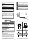
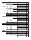
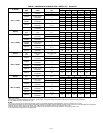
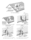
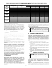
A. Extended Exposed Sidewall Pipes
Sidewall combustion-air and vent pipe terminations may be
extended beyond area shown in Fig. 40 or 41 in outside ambient by
insulating pipes as indicated in Table 8.
1. Determine combustion-air and vent pipe diameters, as
stated above, using total pipe length and number of elbows.
2. Using winter design temperature (used in load calculations),
find appropriate temperature for your application and fur-
nace model.
3. Determine required insulation thickness for exposed pipe
lengths.
NOTE: Pipe length (ft) specified for maximum pipe lengths
located in unconditioned spaces cannot exceed total allowable pipe
length as specified in Table 7.
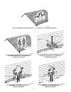
B. Two-Pipe Termination Kit
1. Determine location for termination.
Consideration of the following should be made when
determining an appropriate location for termination kit.
a. Comply with all clearance requirements as stated in
Table 6.
b. Termination kit should be positioned where vent vapors
will not damage plants/shrubs or air conditioning equip-
ment.
c. Termination kit should be positioned so it will not be
affected by wind eddy (such as inside building corners)
or accumulation of airborne leaves or light snow, or
allow recirculation of flue gases.
d. Termination kit should be positioned where it will not be
damaged by or subjected to foreign objects, such as
stones, balls, etc.
e. Termination kit should be positioned where vent vapors
are not objectionable.
2. Cut 2 holes, 1 for each pipe, of appropriate size for pipe size
being used.
3. Loosely install elbow in bracket and place assembly on
combustion-air pipe.
Roof terminations—Loosely install pipe coupling on prop-
erly cut vent pipe. Coupling must be positioned so bracket
will mount as shown in Fig. 37.
For applications using combustion-air pipe option indicated
by dashed lines in Fig. 37, install 90° street elbow into 90°
elbow, making U-fitting. A 180° U-fitting may be used.
Sidewall terminations—Install bracket as shown in Fig. 40
or 41.
For applications using vent pipe option indicated by dashed
lines in Fig. 40, rotate vent elbow 90° from position shown
in Fig. 40.
4. Disassemble loose pipe fittings. Clean and cement using
same procedures as used for system piping.
5. Check required dimensions as shown in Fig. 37, 40, or 41.
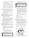
C. Concentric Vent/Air Termination Kit
1. Determine location for termination.
Consideration of the following should be made when
determining an appropriate location for termination kit.
a. Comply with all clearance requirements as stated in
Table 6.
b. Termination kit should be positioned where vent vapors
will not damage plants/shrubs or air conditioning equip-
ment.
c. Termination kit should be positioned so it will not be
affected by wind eddy (such as inside building corners)
or accumulation of airborne leaves or light snow, or
allow recirculation of flue gases.
d. Termination kit should be positioned where it will not be
damaged by or subjected to foreign objects, such as
stones, balls, etc.
e. Termination kit should be positioned where vent vapors
are not objectionable.
2. Cut one 4-in. diameter hole for 2-in. kit, or one 5-in.
diameter hole for 3-in. kit.
3. Loosely assemble concentric vent/air termination compo-
nents together using instructions in kit.
4. Slide assembled kit with rain shield REMOVED through
hole.
NOTE: Do not allow insulation or other materials to accumulate
inside of pipe assembly when installing it through hole.
Roof terminations—Locate assembly through roof to ap-
propriate height as shown in Fig. 38.
Sidewall terminations—Locate assembly through sidewall
with rain shield positioned no more than 1-in. from wall as
shown in Fig. 38.
5. Disassemble loose pipe fittings. Clean and cement using
same procedures as used for system piping.
6. Check required dimensions as shown in Fig. 38 or 39.
IV. MULTIVENTING AND VENT TERMINATIONS
When 2 or more 355MAV Furnaces are vented near each other,
each furnace must be individually vented. NEVER common vent
or breach vent 355MAV furnaces. When 2 or more 355MAV
—29—