


c. Cooling off-delay-When the ″call for cooling″ is satis-
fied and there is a demand for dehumidification, the
cooling blower-off delay is decreased from 90 seconds to
5 seconds.
VI. CONTINUOUS BLOWER MODE
When the R to G circuit is closed by the thermostat, the blower
motor BLWM will operate at continuous-blower airflow. Continu-
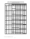
ous blower airflow selection is initially based on the CF selection
shown in Fig. 58. Factory default is shown in Fig. 58. Terminal
EAC-1 is energized as long as the blower motor BLWM is
energized.
During a call for heat, the blower BLWM will transition the blower
motor BLWM to continuous blower airflow, low-heat airflow, or
the midrange airflow, whichever is lowest. The blower motor
BLWM will remain ON until the main burners ignite then shut
OFF and remain OFF for the blower-ON delay (60 seconds in
low-heat and 35 seconds in high-heat) allowing the furnace heat
exchangers to heat more quickly, then restarts at the end of the
blower-ON delay period at low-heat or high-heat airflow respec-
tively.
The blower motor BLWM will revert to continuous-blower airflow
after the heating cycle is completed. In high-heat, the furnace
control CPU will drop the blower motor BLWM to low-heat
airflow during the selected blower-OFF delay period before
transitioning to continuous-blower airflow.
When the thermostat ″calls for high-cooling″, the blower motor
BLWM will operate at high-cooling airflow. When the thermostat
is satisfied, the blower motor BLWM will operate an additional 90
seconds at high-cooling airflow before transitioning back to
continuous-blower airflow.
When the R to G circuit is opened, the blower motor BLWM will
continue operating for an additional 5 seconds, if no other function
requires blower motor BLWM operation.
Continuous Blower Speed Selection from Thermostat
To select different continuous-blower speeds from the room
thermostat, momentarily turn off the FAN switch or push-
button on the room thermostat for 1-3 seconds after the
blower motor BLWM is operating. The furnace control
CPU will shift the continuous-blower airflow from the
factory setting to the next highest CF selection airflow as
shown in Fig. 58. Momentarily turning off the FAN switch
again at the thermostat will shift the continuous-blower
airflow up one more increment. If you repeat this procedure
enough, you will eventually shift the continuous-blower
airflow to the lowest CF selection as shown in Fig. 58. The
selection can be changed as many times as desired and is
stored in the memory to be automatically used following a
power interruption.
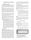
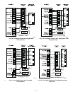
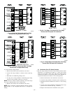
VII. HEAT PUMP
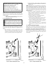
See Fig. 52-55 for thermostat connections.
When installed with a heat pump, the furnace control automatically
changes the timing sequence to avoid long blower off times during
demand defrost cycles. Whenever W/W1 is energized along with
Y1 or Y/Y2, the furnace control CPU will transition to or bring on
the blower motor BLWM at cooling airflow, low-heat airflow, or
the midrange airflow, whichever is the lowest. The blower motor
BLWM will remain on until the main burners ignite, then shut OFF
and remain OFF for 25 seconds before coming back on at heating
airflow. When the W/W1 input signal disappears, the furnace
control begins a normal inducer post-purge period while changing
the blower airflow. If Y/Y2 input is still energized, the furnace
control CPU will transition the blower motor BLWM airflow to
cooling airflow. If Y/Y2 input signal disappears and the Y1 input
is still energized, the furnace control CPU will transition the
blower motor BLWM to low-cooling airflow. If both the Y1 and
Y/Y2 signals disappear at the same time, the blower motor BLWM
will remain on at low-heat airflow for the selected blower-OFF
delay period. At the end of the blower-OFF delay, the blower
motor BLWM will shut OFF unless G is still energized, in which
case the blower motor BLWM will operate at continuous blower
airflow.
VIII. COMPONENT TEST
The furnace features a component test system to help diagnose a
system problem in the case of a component failure. To initiate the
component test procedure, ensure that there are no thermostat
inputs to the control and all time delays have expired. Turn on
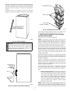
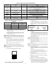
setup switch SW1-6 (See Fig. 32.)
NOTE: The component test feature will not operate if the control
is receiving any thermostat signals or until all time delays have
expired.
The component test sequence is as follows:
a. The furnace control CPU turns the inducer motor IDM
ON at medium speed and keeps it ON through step c.
b. After waiting 15 seconds, the furnace control CPU turns
the hot surface igniter ON for 15 seconds, then OFF.
c. The furnace control CPU then turns the blower motor
BLWM ON at midrange airflow for 15 seconds, then
OFF.
d. After shutting the blower motor BLWM OFF, the
furnace control CPU shuts the inducer motor IDM OFF.
NOTE: The EAC terminals are energized when the blower is
operating.
After the component test is completed, 1 or more status codes (11,
25, 41, or 42) will flash. See Service Label on blower access panel
or Service/Status Code Instructions for explanation of status codes.
NOTE: To repeat component test, turn setup switch SW1-6 to
OFF and then back ON.
START-UP PROCEDURES
I. GENERAL
1. Furnace must have a 115-v power supply properly con-
nected and grounded.
NOTE: Proper polarity must be maintained for 115-v wiring. If
polarity is incorrect, control status indicator light flashes rapidly
and furnace does not operate.
2. Thermostat wire connections at terminals R, W/W1, G, and
Y/Y2 must be made at 24-v terminal block on furnace
control.
3. Natural gas service pressure must not exceed 0.5 psig
(14-in. wc), but must be no less than 0.16 psig (4.5-in. wc).
4. Blower access panel must be in place to complete 115-v
electrical circuit to furnace.
CAUTION: These furnaces are equipped with a manual
reset limit switch in burner box. This switch opens and
shuts off power to the gas valve if an overheat condition
(flame rollout) occurs in burner enclosure. Correct inad-
equate combustion-air supply or improper venting condi-
tion before resetting switch. DO NOT jumper this switch.
Before operating furnace, check flame rollout manual reset switch
for continuity. If necessary, press button to reset switch.
II. SELECT SETUP SWITCH POSITIONS
A. Air Conditioning (A/C) Setup Switches
The air conditioning setup switches are used to match furnace
airflow to cooling unit used.
—36—