


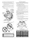


switch is closed. If either a status code 31 or 32 is flashed
when inducer motor is disconnected, the furnace will shut
itself down immediately. Determine the reason pressure
switches did not function properly and correct the condi-
tion.
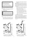
5. Turn off 115-v power to furnace.
6. Reconnect inducer motor wire harness. Reinstall furnace
access door.
7. Turn on 115-v power to furnace.
8. Reset thermostat to desired temperature.
CHECKLIST
1. Put away tools and instruments. Clean up debris.
2. Verify flame rollout manual reset switch has continuity.
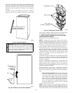
3. Verify that blower and main access doors are properly
installed.
4. Cycle test furnace with room thermostat.
5. Check operation of accessories per manufacturer’s instruc-
tions.
6. Review User’s Manual with owner.
7. Leave literature packet near furnace.
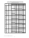
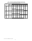
TABLE 13—GAS RATE CU FT/HR
SECONDS
FOR 1
REVOLUTION
SIZE OF TEST DIAL
SECONDS
FOR 1
REVOLUTION
SIZE OF TEST DIAL
1
cu ft
2
cu ft
5
cu ft
1
cu ft
2
cu ft
5
cu ft
10
11
12
13
14
360
327
300
277
257
720
655
600
555
514
1800
1636
1500
1385
1286
50
51
52
53
54
72
71
69
68
67
144
141
138
136
133
360
355
346
340
333
15
16
17
18
19
240
225
212
200
189
480
450
424
400
379
1200
1125
1059
1000
947
55
56
57
58
59
65
64
63
62
61
131
129
126
124
122
327
321
316
310
305
20
21
22
23
24
180
171
164
157
150
360
343
327
313
300
900
857
818
783
750
60
62
64
66
68
60
58
56
54
53
120
116
112
109
106
300
290
281
273
265
25
26
27
28
29
144
138
133
129
124
288
277
267
257
248
720
692
667
643
621
70
72
74
76
78
51
50
48
47
46
103
100
97
95
92
257
250
243
237
231
30
31
32
33
34
120
116
113
109
106
240
232
225
218
212
600
581
563
545
529
80
82
84
86
88
45
44
43
42
41
90
88
86
84
82
225
220
214
209
205
35
36
37
38
39
103
100
97
95
92
206
200
195
189
185
514
500
486
474
462
90
92
94
96
98
40
39
38
38
37
80
78
76
75
74
200
196
192
188
184
40
41
42
43
44
90
88
86
84
82
180
176
172
167
164
450
439
429
419
409
100
102
104
106
108
36
35
35
34
33
72
71
69
68
67
180
178
173
170
167
45
46
47
48
49
80
78
76
75
73
160
157
153
150
147
400
391
383
375
367
110
112
116
120
33
32
31
30
65
64
62
60
164
161
155
150
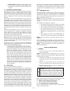
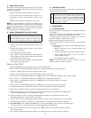
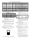
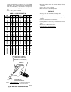
Fig. 65—Amp Draw Check with Ammeter
A96316
R Y W G
10 TURNS
THERMOSTAT SUBBASE
TERMINALS WITH
THERMOSTAT REMOVED
(ANITICIPATOR, CLOCK, ETC.,
MUST BE OUT OF CIRCUIT.)
HOOK-AROUND
AMMETER
EXAMPLE:
5.0 AMPS ON AMMETER
10 TURNS AROUND JAWS
=
0.5 AMPS FOR THERMOSTAT
ANTICIPATOR SETTING
FROM UNIT 24-V
CONTROL TERMINALS
—46—