


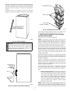
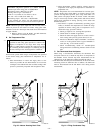
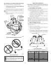

g. Jumper R and W/W1 and W2 thermostat connections on
furnace control. (See Fig. 32.) This keeps furnace locked
in high-heat operation.
h. Turn high-heat adjusting screw (3/32 hex Allen wrench)
counterclockwise (out) to decrease input rate or clock-
wise (in) to increase rate.
NOTE: DO NOT set high-heat manifold pressure less than 3.2-in.
wc or more than 3.8-in. wc for natural gas. If manifold pressure is
outside this range, change main burner orifices to obtain manifold
pressures in this range.
i. When correct input is obtained, replace caps that conceal
gas valve regulator adjustment screws. Main burner
flame should be clear blue, almost transparent. (See Fig.
64.)
j. Remove jumpers R-to-W/W1 and R-to-W2.
3. Verify natural gas input rate by clocking gas meter.
NOTE: Be sure all pressure tubing, combustion-air and vent
pipes, and burner enclosure front are in place when checking input
by clocking gas meter.
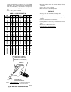
a. Calculate high-altitude adjustment (if required).
UNITED STATES
At altitudes above 2000 ft, this furnace has been ap-
proved for a 2 percent derate for each 1000 ft above sea
level. See Table 12 for derate multiplier factor and
example.
EXAMPLE: 100,000 BTUH HIGH-HEAT INPUT FURNACE IN-
STALLED AT 4300 FT.
Furnace Input Rate
at Sea Level
X
Derate
Multiplier
Factor
=
Furnace Input Rate
at Installation
Altitude
100,000 X 0.91 = 91,000
CANADA
At installation altitudes from 2000 to 4500 ft, this
furnace must be derated 5 percent by an authorized Gas
Conversion Station or Dealer. To determine correct input
rate for altitude, see example above and use 0.95 as
derate multiplier factor.
b. Reinstall burner box cover.
NOTE: Clocking gas input rate MUST always be performed with
the burner box cover INSTALLED.
c. Check that gas valve adjustment caps are in place for
proper input to be clocked.
d. Obtain average heat value (at altitude) from local gas
supplier.
NOTE: Be sure heating value of gas used for calculations is
correct for your altitude. Consult local gas utility for altitude
adjustment of gas heating value.
e. Check and verify orifice size in furnace. NEVER AS-
SUME THE ORIFICE SIZE. ALWAYS CHECK AND
VERIFY.
f. Turn off all other gas appliances and pilots.
g. Turn setup switch SW1-2 to ON position. (See Fig. 32.)
This keeps furnace locked in low-heat operation.
h. Jumper R-to-W/W1
i. Let furnace run for 3 minutes in low-heat operation.
j. Measure time (in sec) for gas meter to complete 1
revolution. Note reading.
k. Refer to Table 13 for cubic ft of gas per hr.
l. Multiply gas rate cu ft/hr by heating value (Btu/cu ft).
m. Turn setup switch SW1-2 to OFF position and jumper R
and W/W1 and W2 thermostat connections. (See Fig.
32.) This keeps furnace locked in high-heat operation.
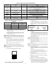
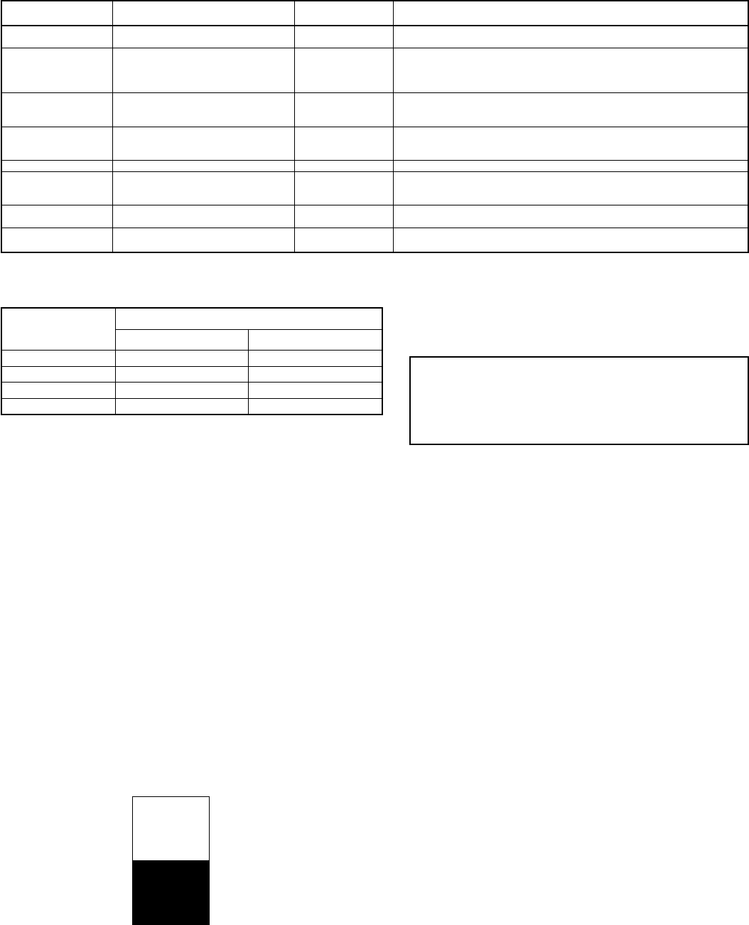
Repeat items i through l for high-heat operation.Fig. 59—Example of Setup Switch in OFF Position
A95198
1
OFF
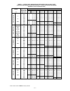
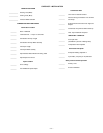
TABLE 9—FURNACE SETUP SWITCH DESCRIPTION
SETUP
SWITCH NO.
SWITCH
NAME
NORMAL
POSITION
DESCRIPTION
OF USE
SW1-1 Status Code Recovery OFF
Turn ON to retrieve up to 7 stored status codes for troubleshooting
assistance when R thermostat lead is disconnected.
SW1-2 Adaptive Heat Mode OFF
Allows 2-stage operation with a single stage thermostat.
Turn ON when using 2 stage thermostat to allow Low Heat opera-
tion when R to W/W1 closes and High Heat operation when R to
W/W1 and W2 close.
SW1-3
Low Heat
Rise Adjust
OFF
Turn ON to increase Low Heat airflow by 18 percent. This compen-
sates for increased return air temperature caused with bypass hu-
midifier.
SW1-4 Comfort/Efficiency Adjustment ON
Turn ON to decrease Low Heat airflow by 7 percent and High Heat
airflow 8 percent for maximum comfort. On 040 unit will decrease
Low-Heat Airflow 11 percent and High-Heat Airflow 10 percent.
SW1-5 CFM per ton adjust OFF Turn ON for 400 CFM per ton. Turn OFF for 350 CFM per ton.
SW1-6 Component Self-Test OFF
Turn ON to initiate Component Self-Test for troubleshooting assis-
tance when R thermostat lead is disconnected.
Turn OFF when Self-Test is completed.
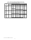
SW1-7 Blower OFF delay ON or OFF
Control blower Off Delay time. Used in conjunction with SW1-8. See
Table 10.
SW1-8 Blower OFF delay ON or OFF
Control blower Off Delay time. Used in conjunction with SW1-7. See
Table 10.
TABLE 10—BLOWER OFF DELAY SETUP SWITCH
POSITION
DESIRED HEATING
MODE BLOWER
OFF DELAY (SEC)
SETUP SWITCH (SW1-7 AND SW1-8) POSITION
SW1-7 SW1-8
90 OFF OFF
120 ON OFF
150 OFF ON
180 ON ON
—41—
→