


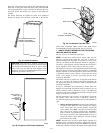
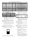
C. Setup Switches (SW1)
The furnace control has 8 setup switches that may be set to meet
the application requirements. Position these setup switches for the
appropriate requirement.
1. Remove main furnace door and blower access panel.
2. Locate setup switches on furnace control. (See Fig. 32.)
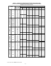
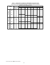
3. See Table 9 for setup switch description. (See Fig. 31 and
59.)
4. Replace main furnace door and blower access panel.
NOTE: If a bypass humidifier is used, setup switch SW1-3 (Low
HEAT Rise Adjust) should be in ON position. This compensates
for the increased temperature in return air resulting from bypass.
NOTE: If modulating dampers are used, blower motor automati-
cally compensates for modulating dampers.
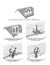
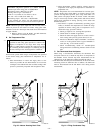
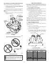
III. PRIME CONDENSATE TRAP WITH WATER
CAUTION: Condensate trap must be PRIMED or
proper draining may not occur. The condensate trap has 2
internal chambers which can ONLY be primed by pour-
ing water into the inducer drain side of condensate trap.
1. Remove upper inducer housing drain connection cap. (See
Fig. 60.)
2. Connect field-supplied 1/2-in. ID tube to upper inducer
housing drain connection.
3. Insert field-supplied funnel into tube.
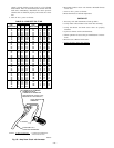
4. Pour 1 quart of water into funnel/tube. Water should run
through inducer housing, overfill condensate trap, and flow
into open field drain. (See Fig. 61.)
5. Remove funnel and tube from inducer housing and replace
drain connection cap and clamp.
IV. PURGE GAS LINES
If not previously done, purge the lines after all connections have
been made and check for leaks.
WARNING: Never purge a gas line into a combustion
chamber. Never test for gas leaks with an open flame. Use
a commercially available soap solution made specifically
for the detection of leaks to check all connections. Failure
to follow this warning could result in fire, explosion,
personal injury, or death.
V. ADJUSTMENTS
A. Set Gas Input Rate
Furnace gas input rate on rating plate is for installations at altitudes
up to 2000 ft.
In the U.S.A., the input rating for altitudes above 2000 ft must be
reduced by 2 percent for each 1000 ft above sea level.
In Canada, the input rating must be derated by 5 percent for
altitudes of 2000 ft to 4500 ft above sea level.
Adjust manifold pressure to obtain input rate.
Furnace input rate must be within ±2 percent of input on furnace
rating plate.
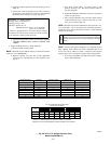
1. Determine natural gas orifice size and manifold pressure for
correct input.
a. Obtain average heat value (at installed altitude) from
local gas supplier.
b. Obtain average specific gravity from local gas supplier.
c. Verify furnace model. Table 11 can only be used for
model 355MAV Furnaces.
d. Find installation altitude in Table 11.
NOTE: For Canada altitudes of 2000 to 4500 ft, use U.S.A.
altitudes of 2001 to 3000 ft in Table 11.
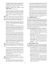
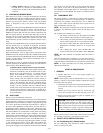
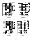
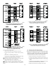
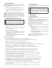
Notes for Fig. 50-57:
1. Heat pump MUST have a high pressure switch for dual fuel applications.
2. Refer to outdoor equipment Installation Instructions for additional information and setup procedure.
3. Select the ″ZONE″ position on the two-speed heat pump control.
4. Outdoor Air Temperature Sensor must be attached in all dual fuel applications.
5. Dip switch No.1 on Thermidistat should be set in OFF position for air conditioner installations. This is factory default.
6. Dip switch No. 1 on Thermidistat should be set in ON position for heat pump installations.
7. Dip switch No. 2 on Thermidistat should be set in OFF position for single-speed compressor operation.
This is factory default.
8. Dip switch No. 2 on Thermidistat should be set in ON position for two-speed compressor operation.
9. Configuration Option No. 10 ″Dual Fuel Selection″ must be turned ON in all dual fuel applications.
10. NO connection should be made to the furnace HUM terminal when using a Thermidistat.
11. Optional connection. If wire is connected, dip switch SW1-2 on furnace control should be set in ON position
to allow Thermidistat/Thermostat to control furnace staging.
12. Optional connection. If wire is connected, ACRDJ jumper on furnace control should be removed to allow
Thermidistat/Thermostat to control outdoor unit staging.
13. Furnace must control its own high-stage heating operation via furnace control algorithm. This is factory default.
14. The RVS Sensing terminal ″L″ should not be connected. This is internally used to sense defrost operation.
15. DO NOT SELECT the ″FURNACE INTERFACE″ or ″BALANCE POINT″ option on the two-speed heat pump
control board. This is controlled internally by the Thermidistat/Dual Fuel Thermostat.
16. Dip switch D on Dual Fuel Thermostat should be set in OFF position for single-speed compressor operation.
This is factory default.
17. Dip switch D on Dual Fuel Thermostat should be set in ON position for two-speed compressor operation.
—39—
→
→