


When the thermostat is satisfied, the R-to-G-and-Y circuits
are opened. The outdoor unit will stop, and furnace blower
motor BLWM will continue operating at cooling airflow for
an additional 90 sec. Jumper Y/Y2 to DHUM to reduce the
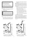
cooling off-delay to 5 seconds. (See Fig. 32.)
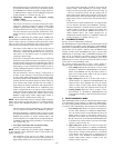
2. Single-Stage Thermostat and Two-Speed Cooling
(Adaptive Mode)
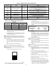
(See Fig. 57 for thermostat connections.)
This furnace can operate a two-speed cooling unit with a
single-stage thermostat because the furnace control CPU
includes a programmed adaptive sequence of controlled
operation, which selects low-cooling or high-cooling opera-
tion. This selection is based upon the stored history of the
length of previous cooling period of the single-stage ther-
mostat.
NOTE: The air conditioning relay disable jumper ACRDJ must
be connected to enable the adaptive cooling mode in response to a
call for cooling. (See Fig. 32.) When in place the furnace control
CPU can turn on the air conditioning relay ACR to energize the
Y/Y2 terminal and switch the outdoor unit to high-cooling.
The furnace control CPU can start up the cooling unit in
either low- or high-cooling. If starting up in low-cooling,
the furnace control CPU determines the low-cooling on-
time (from 0 to 20 minutes) which is permitted before
switching to high-cooling.
If the power is interrupted, the stored history is erased and
the furnace control CPU will select low-cooling for up to 20
minutes and then energize the air conditioning relay ACR to
energize the Y/Y2 terminal and switch the outdoor unit to
high-cooling, as long as the thermostat continues to call for
cooling. Subsequent selection is based on stored history of
the thermostat cycle times.
The wall thermostat ″calls for cooling″, closing the R to
G-and-Y circuits. The R to Y1 circuit starts the outdoor unit
on low-cooling speed, and the R to G-and-Y1 circuits starts
the furnace blower motor BLWM at low-cooling airflow
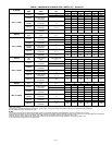
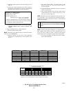
which is the true on-board CF selection as shown in Fig. 58.
If the furnace control CPU switches from low-cooling to
high-cooling, the furnace control CPU will energize the air
conditioning relay ACR. When the air conditioning relay
ACR is energized the R to Y1-and-Y2 circuits switch the
outdoor unit to high-cooling speed, and the R to G-and-Y1-
and-Y/Y2 circuits transition the furnace blower motor
BLWM to high-cooling airflow. High-cooling airflow is
based on the A/C selection shown in Fig. 58.
NOTE: When transitioning from low-cooling to high-cooling the
outdoor unit compressor will shut down for 1 minute while the
furnace blower motor BLWM transitions to run at high-cooling
airflow.
The electronic air cleaner terminal EAC-1 is energized with
115 vac whenever the blower motor BLWM is operating.
When the thermostat is satisfied, the R to G-and-Y circuit
are opened. The outdoor unit stops, and the furnace blower
BLWM and electronic air cleaner terminal EAC-1 will
remain energized for an additional 90 seconds. Jumper Y1
to DHUM to reduce the cooling off-delay to 5 seconds. (See
Fig. 32.) (See Fig. 32.)
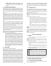
3. Two-Stage Thermostat and Two-Speed Cooling
(See Fig. 56 for thermostat connections)
NOTE: The air conditioning relay disable jumper ACRDJ must
be disconnected to allow thermostat control of the outdoor unit
staging. (See Fig. 32.)
The thermostat closes the R to G and-Y1 circuits for
low-cooling or closes the R to G and-Y1-and-Y2 circuits for
high-cooling. The R to Y1 circuit starts the outdoor unit on
low-cooling speed, and the R to G-and-Y1 circuit starts the
furnace blower motor BLWM on low-cooling airflow
which is the true on-board CF selection as shown in Fig. 58
. The R to Y1-and-Y2 circuits start the outdoor unit on
high-cooling speed, and the R to G-and-Y/Y2 circuits start
the furnace blower motor BLWM at high-cooling ariflow.
High-cooling airflow is based on the A/C selection shown
in Fig. 58.
The electronic air cleaner terminal EAC-1 is energized with
115 vac whenever the blower motor BLWM is operating.
When the thermostat is satisfied, the R to G-and-Y1 or R to
G-and-Y1-and-Y2 circuits are opened. The outdoor unit
stops, and the furnace blower BLWM and electronic air
cleaner terminal EAC-1 will remain energized for an
additional 90 seconds. Jumper Y1 to DHUM to reduce the
cooling off-delay to 5 seconds. (See Fig. 32.)
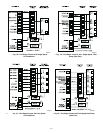
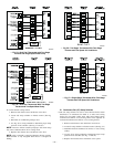
IV. THERMIDISTAT MODE
See Fig. 50-53 for Thermidistat connections.
The dehumidification output, DHUM on the Thermidistat should
be connected to the furnace control thermostat terminal DHUM.
When there is a dehumidify demand, the DHUM input is activated,
which means 24 vac signal is removed from the DHUM input
terminal. In other words, the DHUM input logic is reversed. The
DHUM input is turned ON when no dehumidify demand exists.
Once 24 vac is detected by the furnace control on the DHUM
input, the furnace control operates in Thermidistat mode. If the
DHUM input is low for more than 48 hours, the furnace control
reverts back to non-Thermidistat mode.
The cooling operation described in item 3. above applies to
operation with a Thermidistat. The exceptions are listed below:
a. Low cooling-When the R to G-and-Y1 circuit is closed
and there is a demand for dehumidification, the furnace
blower motor BLWM will drop the blower airflow to
86% of low-cooling airflow which is the true on-board
CF selection as shown in Fig. 58.
b. High cooling-When the R to G-and Y/Y2 circuit is
closed and there is a demand for dehumidification, the
furnace blower motor BLWM will drop the blower
airflow to 86% of high-cooling airflow. High-cooling
airflow is based on the A/C selection shown in Fig. 58.
c. Cooling off-delay-When the ″call for cooling″ is satis-
fied and there is a demand for dehumidification, the
cooling blower-off delay is decreased from 90 seconds to
5 seconds.
V. SUPER-DEHUMIDIFY MODE
Super-Dehumidify mode can only be entered if the furnace control
is in Thermidistat mode and there is a demand for dehumidifica-
tion. The cooling operation described in item 3. above also applies
to operation with a Thermidistat. The exceptions are listed below:
a. Low cooling-When the R to Y1 circuit is closed, R to G
circuit is open, and there is a demand for dehumidifica-
tion, the furnace blower motor BLWM will drop the
blower airflow to 65% of low-cooling airflow for a
maximum of 10 minutes each cooling cycle or until the
R to G circuit closes or the demand for dehumidification
is satisfied. Low-cooling airflow is the true on-board CF
selection as shown in Fig. 58.
b. High cooling-When the R to Y/Y2 cicuit is closed, R to
G circuit is open, and there is a demand for dehumidi-
fiation, the furnace blower motor BLWM will drop the
blower to 65% of high-cooling airflow for a maximum
of 10 minutes each cooling cycle or until the R to G
circuit closes or the demand for dehumidification is
satisfied. High-cooling airflow is based on the A/C
selection shown in Fig. 58.
—35—