


Secure ductwork with proper fasteners for type of ductwork used.
Seal supply- and return-duct connections to furnace with code
approved tape or duct sealer.
Flexible connections should be used between ductwork and
furnace to prevent transmission of vibration. Ductwork passing
through unconditioned space should be insulated to enhance
system performance. When air conditioning is used, a vapor
barrier is recommended.
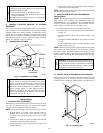
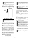
Maintain a 1-in. clearance from combustible materials to supply air
ductwork for a distance of 36 in. horizontally from the furnace. See
NFPA 90B or local code for further requirements.
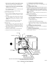
For a furnace not equipped with a cooling coil, the outlet duct shall
be provided with a removable access panel. This opening shall be
accessible when the furnace is installed and shall be of such a size
that the heat exchanger can be viewed for possible openings using
light assistance or a probe can be inserted for sampling the air
stream. The cover attachment shall prevent leaks.
B. Ductwork Acoustical Treatment
Metal duct systems that do not have a 90 degree elbow and 10 ft
of main duct to the first branch take-off may require internal
acoustical lining. As an alternative, fibrous ductwork may be used
if constructed and installed in accordance with the latest edition of
SMACNA construction standard on fibrous glass ducts. Both
acoustical lining and fibrous ductwork shall comply with NFPA
90B as tested by UL Standard 181 for Class 1 Rigid air ducts.
C. Supply Air Connections
UPFLOW FURNACES
Connect supply-air duct to 3/4-in. flange on furnace supply-air
outlet. The supply-air duct attachment must ONLY be connected
to furnace supply-/outlet-air duct flanges or air conditioning coil
casing (when used). DO NOT cut main furnace casing to attach
supply side air duct, humidifier, or other accessories. All accesso-
ries MUST be connected external to furnace main casing.
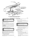
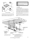
DOWNFLOW FURNACES
Connect supply-air duct to supply-air opening on furnace. The
supply-air duct attachment must ONLY be connected to furnace
supply\outlet or air conditioning coil casing (when used), when
installed on non-combustible material. When installed on combus-
tible material, supply-air duct attachment must ONLY be con-
nected to an accessory subbase or factory approved air condition-
ing coil casing. DO NOT cut main furnace casing to attach
supplyside air duct, humidifier, or other accessories. All accesso-
ries MUST be connected external to furnace main casing. Supply
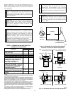
air opening duct flanges must be modified per Fig. 22
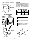
HORIZONTAL FURNACES
Connect supply-air duct to supply air opening on furnace. The
supply-air duct attachment must ONLY be connected to furnace
supply/outlet or air conditioning coil casing (when used). DO NOT
cut main furnace casing to attach supply side air duct, humidifier,
or other accessories. All accessories MUST be connected external
to furnace main casing.
D. Return Air Connections
WARNING: Never connect return-air ducts to the back
of the furnace. Return-air duct connections on furnace
side(s) permitted in upflow applications only. A failure to
follow this warning could result in fire, personal injury, or
death.
UPFLOW FURNACES
The return-air duct must be connected to bottom , sides (left or
right), or a combination of bottom and side(s) of main furnace
casing. Bypass humidifier may be attached into unused side return
air portion of the furnace casing. DO NOT connect any portion of
return-air duct to back of furnace casing.
DOWNFLOW AND HORIZONTAL FURNACES
The return-air duct must be connected to return-air opening
provided. DO NOT cut into casing sides or back to attach any
portion of return-air duct. Bypass humidifier connections should
be made at ductwork or coil casing sides exterior to furnace.
E. Filter Arrangement
WARNING: Never operate unit without a filter or with
filter access door removed. Failure to follow this warning
can cause fire, personal injury, or death.
The air filter arrangement will vary due to application, furnace
orientation, and filter type. The filter may be installed in an
external Filter/Media cabinet (if provided) or the furnace blower
compartment. Factory supplied washable filters are shipped in the
blower compartment.
If a factory-supplied external Filter/Media cabinet is provided,
instructions for its application, assembly, and installation are
packaged with the cabinet. The Filter/Media cabinet can be used
with the factory-supplied washable filter or a factory-specified
high-efficiency disposable filter (see cabinet instructions).
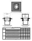
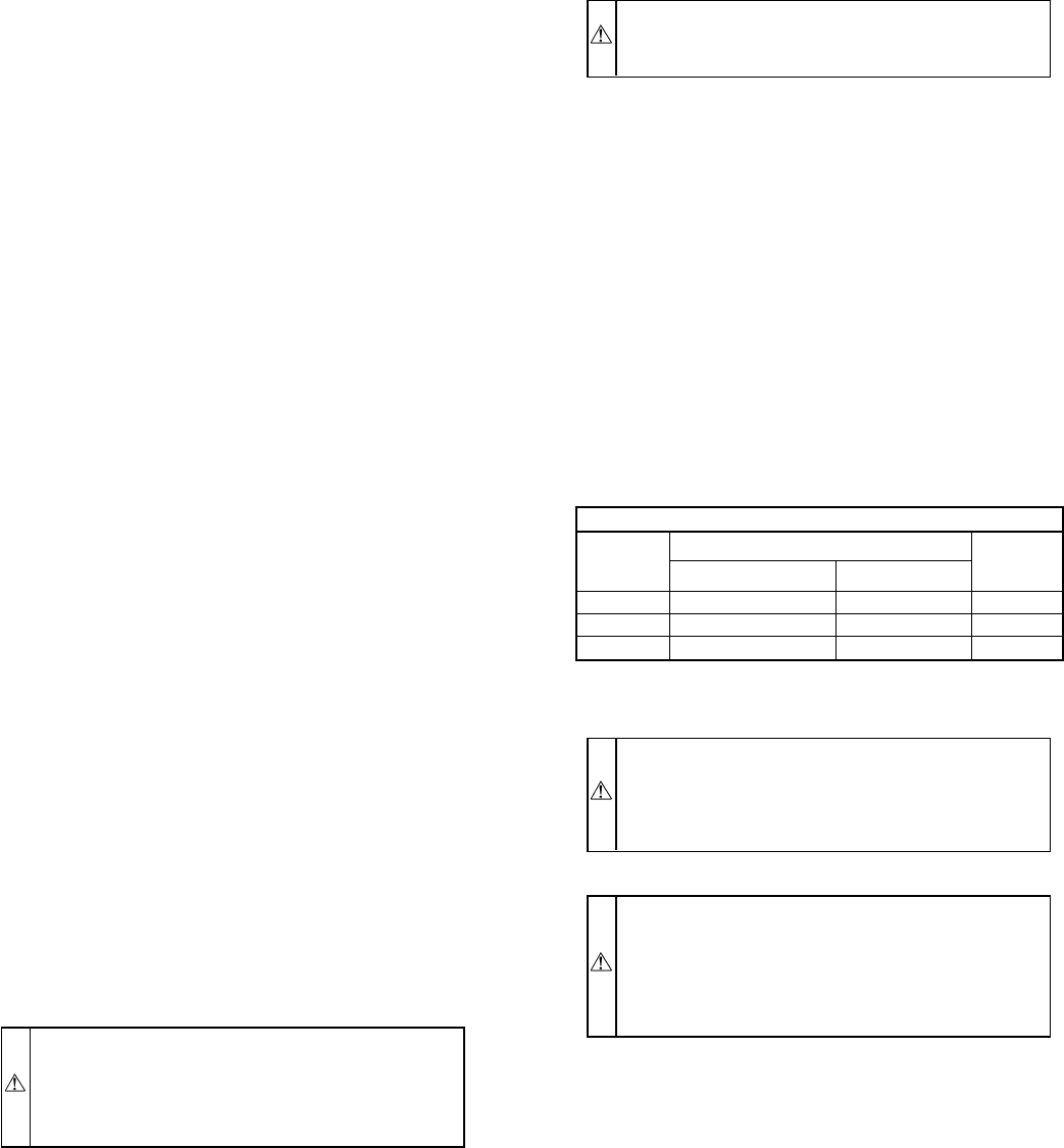
If installing the filter in the furnace blower compartment, deter-
mine location for filter and relocate filter retaining wire, if
necessary. See Table 2 to determine correct filter size for desired
filter location. Table 2 indicates filter size, location, and quantity
shipped with this furnace. See Fig. 2 for location and size of
bottom and side return-air openings.
CAUTION: Use care when cutting support rods in filters
to protect against flying pieces and sharp rod ends. Wear
safety glasses, gloves, and appropiate protective clothing.
Failure to follow this caution could result in personal
injury.
CAUTION: For airflow requirements above 1800 CFM,
see Air Delivery table in Product Data literature for
specific use of single side inlets. The use of both side
inlets, a combination of 1 side and the bottom, or the
bottom only will ensure adequate return air openings for
airflow requirements above 1800 CFM.
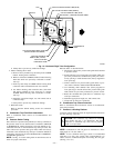
NOTE: Side return-air openings can ONLY be used in UPFLOW
configurations. Install filter(s) as shown in Fig. 24.
For bottom return-air applications, filter may need to be cut to fit
some furnace widths. Install filter as shown in Fig. 25.
NOTE: Remove and discard bottom closure panel when bottom
inlet is used.
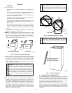
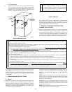
F. Bottom Closure Panel
These furnaces are shipped with bottom closure panel installed in
bottom return-air opening. This panel MUST be in place when side
return air is used.
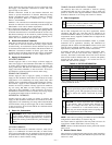
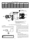
TABLE 2—FILTER INFORMATION
AIR FILTER LOCATED IN BLOWER COMPARTMENT
Furnace
Casing
Width (In.)
Filter Size (In.)
Filter Type
Framed
Side Return Bottom Return
17-1/2 (1)16X25X1† (1)16X25X1† Cleanable
21 (1)16X25X1* (1)20X25X1† Cleanable
24-1/2 (1or2)16X25X1* (1)24X25X1† Cleanable
* Filters may be field modified by cutting filter material and support rods (3) in
filters. Alternate sizes can be ordered from your distributor or dealer.
† Factory-provided with furnace.
—17—
→
→