


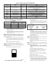
Fig. 65 illustrates an easy method of obtaining thermostat amp
draw measurements. The amp reading should be taken after blower
motor has started and furnace is operating in low-heat.
1. To operate furnace in low-heat, turn setup switch SW1-2 to
ON position (See Fig. 32) and connect ammeter leads
across thermostat subbase R-W.
2. See thermostat manufacturer’s instructions for adjusting the
heat anticipator and for varying heating cycle length.
NOTE: When using an electronic thermostat, set cycle rate for 3
cycles per hr.
3. Return setup switch SW1-2 to OFF position and replace
thermostat on subbase.
CHECK SAFETY CONTROLS
This section covers the safety controls that must be checked before
the installation is complete. The flame sensor, gas valve, and
pressure switches were all checked in the Start-up procedure
section as part of normal operation.
I. CHECK PRIMARY LIMIT CONTROL
This control shuts off the gas control system and energizes the
air-circulating blower motor if furnace overheats.
1. The recommended method of checking this limit control is
to gradually block off return air after furnace has been
operating for a period of at least 5 minutes.
2. As soon as limit control has shut off burners, a 33 status
code will appear on furnace control.
3. The return-air opening should be quickly unblocked to
permit normal air circulation.
By using this method to check the limit control, it can be
established that the limit is functioning properly and the furnace
will operate safely if there is a restricted return-air duct or motor
failure. If the limit control does not function during this test, the
cause must be determined and corrected.
II. CHECK PRESSURE SWITCHES
This control proves operation of the draft inducer. Check switch
operation as follows:
1. Turn off 115-v power to furnace.
2. Remove control access door and disconnect inducer motor
12-pin wire harness at inducer motor.
3. Turn on 115-v power to furnace.
4. Set thermostat to ″call-for-heat.″ When pressure switches
are functioning properly, status code 42 will flash on
furnace control approximately 20 sec after thermostat
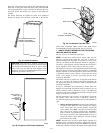
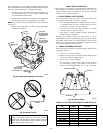
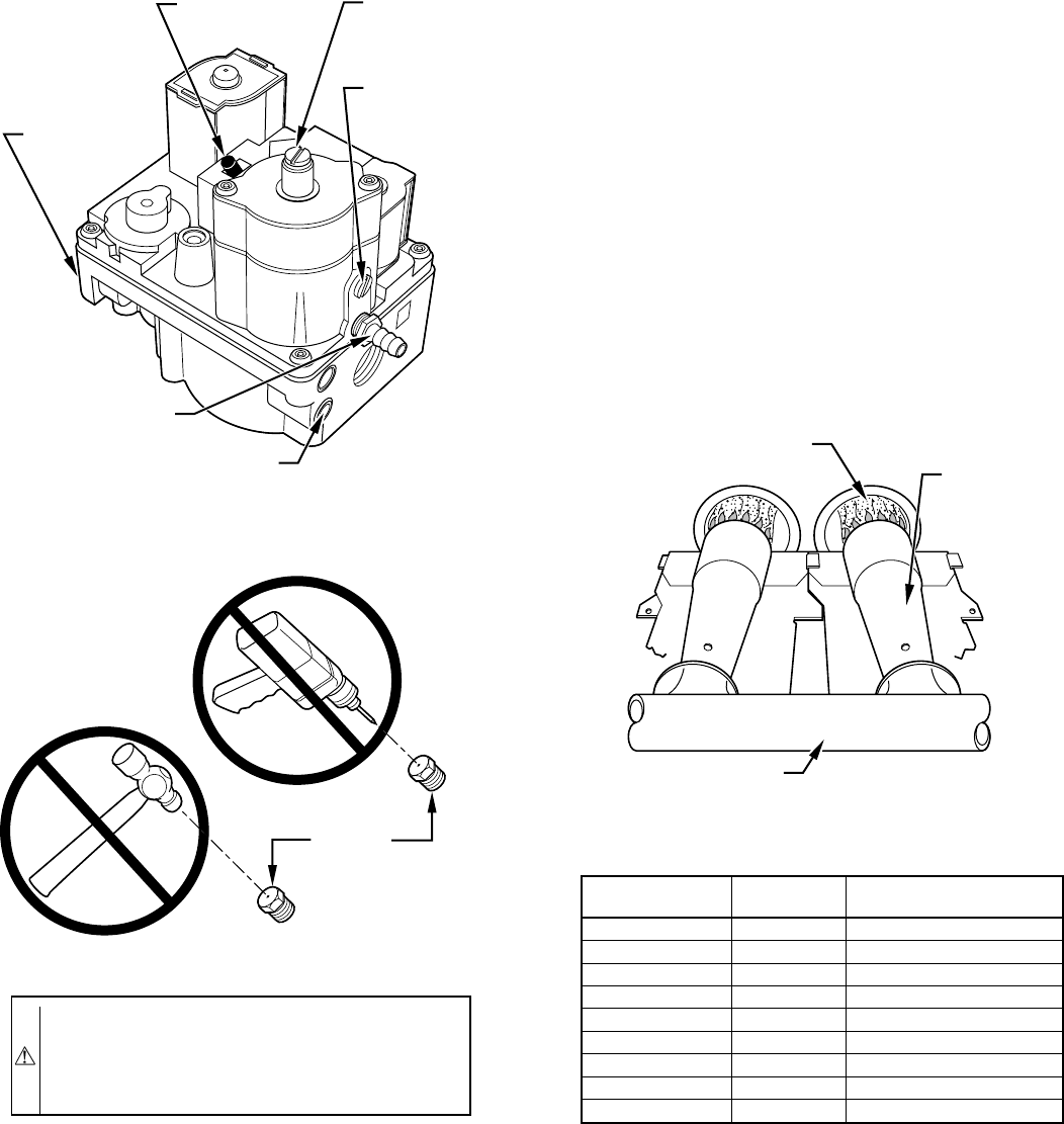
Fig. 62—Redundant Automatic Gas Valve
A97386
ON/OFF
SWITCH
INLET
PRESSURE
TAP
ON
O
F
F
BURNER
ENCLOSURE
REFERENCE
PRESSURE TAP
MANIFOLD
PRESSURE
TAP
LOW-FIRE
ADJUSTMENT
ALLEN SCREW
(UNDER CAP)
HIGH-FIRE
ADJUSTMENT
ALLEN SCREW
(UNDER CAP)
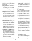
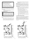
CAUTION: DO NOT redrill orifices. Improper drilling
(burrs, out-of-round holes, etc.) can cause excessive
burner noise and misdirection of burner flames. This can
result in flame impingement of burners and heat exchang-
ers, causing failures. (See Fig. 63.)
A93059
Fig. 63—Burner Orifice
BURNER
ORIFICE
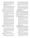
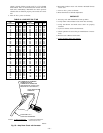
Fig. 64—Burner Flame
A89020
BURNER FLAME
BURNER
MANIFOLD
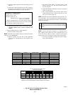
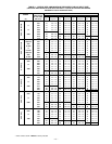
TABLE 12—ALTITUDE DERATE MULTIPLIER FOR U.S.A.
ALTITUDE
(FT)
%OF
DERATE
DERATE MULTIPLIER
FACTOR
0—2000 0 1.00
2001—3000 4—6 0.95
3001—4000 6—8 0.93
4001—5000 8—10 0.91
5001—6000 10—12 0.89
6001—7000 12—14 0.87
7001—8000 14—16 0.85
8001—9000 16—18 0.83
9001—10,000 18—20 0.81
* Derate multiplier factors are based on midpoint altitudes for altitude ranges.
—45—
→