


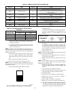

To set the desired cooling airflow:
1. Remove main furnace door and blower access door.
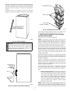
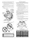
2. Locate A/C setup switches on frunace control. (See Fig.
32.)
3. Determine air conditioning tonnage used.
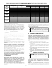
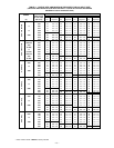
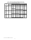
4. Use Fig. 58 or wiring schematic to determine proper setup
position of A/C switches. (See Fig. 31 and 59.)
NOTE: Excessive airflow caused by improper A/C switch setup
may cause condensate blow off in cooling mode.
5. Replace main furnace door and blower access door.
NOTE: EAC-1 terminal is energized whenever blower operates.
HUM terminal is only energized when blower is energized in
heating.
B. Continuous Fan (CF) Setup Switches
The CF setup switches are used to select desired airflow when
thermostat is in continuous fan mode or to select low-cooling
airflow for two-speed cooling units. This setup feature allows
continuous fan airflow or low-cooling airflow to be adjusted. To
set desired continuous fan airflow or low-cooling airflow:
1. Remove main furnace door and blower access door.
2. Locate CF setup switches on furnace control. (See Fig. 32.)
3. Determine desired continuous fan airflow or low-cooling
airflow.
4. Use Fig. 58 or wiring schematic to determine proper setup
position of CF switches. (See Fig. 31 and 59.)
5. Replace main furnace door and blower access panel.
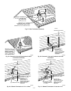
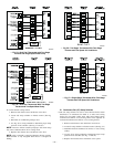
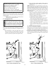
A00279
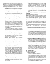
→ Fig. 54—Dual Fuel Thermostat with Two-Stage
Furnace and Single-Speed Heat Pump
A00281
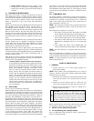
→ Fig. 56—Two-Stage Thermostat With Two-Stage
Furnace and Two-Speed Air Conditioner
See note 2
A00280
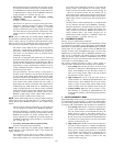
→ Fig. 55—Dual Fuel Thermostat With Two-Stage
Furnace and Two-Speed Heat Pump
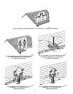
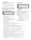
A02348
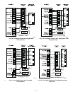
→ Fig. 57—Single-Stage Thermostat With Two-Stage
Furnace and Two-Speed Air Conditioner
—38—
→