


II. 24-V WIRING
Make field 24-v thermostat connections at 24-v terminal block on
furnace control. Y wire from thermostat MUST be connected to
Y/Y2 terminal on furnace control, as shown in Fig. 28, for proper
cooling operation. The 24-v terminal block is marked for easy
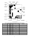
connection of field wiring. (See Fig. 32.) The 24-v circuit contains
a 3-amp, automotive-type fuse located on furnace control. (See
Fig. 32.) Any electrical shorts of 24-v wiring during installation,
service, or maintenance may cause fuse to blow. If fuse replace-
ment is required, use only a fuse of identical size (3 amp) and type.
The furnace control will flash status code 24 when fuse needs
replacement.
NOTE: Use AWG No. 18 color-coded copper thermostat wire for
lengths up to 100 ft. For wire lengths over 100 ft, use AWG No.
16 wire.
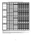
NOTE: For additional thermostat connection diagrams, reference
Fig. 50-57.
III. ACCESSORIES
1. Electronic Air Cleaner (EAC)
The furnace control EAC terminals are energized with 115v
(1.0-amp maximum) during blower operation.
Connect an accessory Electronic Air Cleaner (if used) using
1/4-in. female quick connect terminals to the two male
1/4-in. quick-connect terminals on the control board marked
EAC-1 and EAC-2. The terminals are rated for 115VAC,
1.0 amps maximum and are energized during blower motor
operation. (See Fig. 32.)
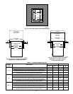
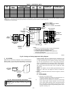
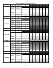
TABLE 4—ELECTRICAL DATA
UNIT
SIZE
VOLTS—
HERTZ—
PHASE
OPERATING
VOLTAGE RANGE
MAXIMUM
UNIT
AMPS
MINIMUM
WIRE
SIZE
MAXIMUM WIRE
LENGTH (FT)‡
MAXIMUM FUSE OR
CKT BKR AMPS**
Maximum* Minimum*
042040 115—60—1 127 104 8.9 14 31 15
042060 115—60—1 127 104 8.9 14 31 15
042080 115—60—1 127 104 8.9 14 31 15
060080 115—60—1 127 104 13.8 12 32 20
060100 115—60—1 127 104 13.8 12 32 20
060120 115—60—1 127 104 13.8 12 32 20
* Permissible limits of voltage range at which unit will operate satisfactorily.
† Unit ampacity = 125 percent of largest operating component’s full load amps plus 100 percent of all other potential operating components’ (EAC, humidifier, etc.) full load
amps.
‡ Length shown is as measured 1 way along wire path between unit and service panel for maximum 2 percent voltage drop.
** Time-delay type is recommended.
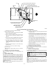
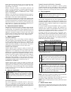
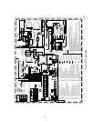
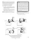
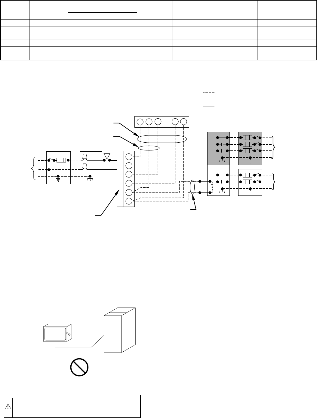
Fig. 28—Heating and Cooling Application Wiring Diagram
A98325
115-V
FIELD-SUPPLIED
DISCONNECT
SWITCH
115-V
SINGLE
PHASE
AUXILIARY
J-BOX
FURNACE
CONTROL
CENTER
TWO WIRE
24-V
TERMINAL
BLOCK
THREE-WIRE
HEATING
ONLY
FIVE
WIRE
NOTE 5
NOTE 1
NOTE
3
THERMOSTAT
TERMINALS
FIELD-SUPPLIED
DISCONNECT
CONDENSING
UNIT
R
W2
WCR GY
GND
GND
GND
GND
FIELD 24-V WIRING
FIELD 115-, 208/230-, 460-V WIRING
FACTORY 24-V WIRING
FACTORY 115-, 208/230-, 460-V WIRING
208/230- OR
460-V
THREE PHASE
208/230-V
SINGLE
PHASE
W/W1
Y/Y2
G
C
NOTES:
1.
2.
3.
4.
5.
Connect Y or Y/Y2 terminal as shown for proper cooling operation.
Proper polarity must be maintained for 115-v wiring.
Use W2 with 2-stage thermostat when zoning.
If any of the original wire, as supplied, must be replaced, use
same type or equivalent wire.
Some thermostats require a "C" terminal connection as shown.
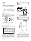
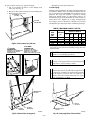
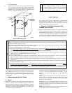
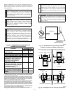
CAUTION: Do not connect aluminum wire between
disconnect switch and furnace. Use only copper wire.
(See Fig. 29.)
A93033
Fig. 29—Disconnect Switch and Furnace
COPPER
WIRE ONLY
ELECTRIC
DISCONNECT
SWITCH
ALUMINUM
WIRE
—20—
→
→