


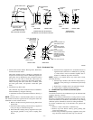

d. Clamp tube to prevent any condensate leakage.
2. Inducer Housing Drain Tube
a. Remove factory-installed cap and clamp from LOWER
inducer housing drain connection.
b. Remove and discard UPPER (molded) inducer housing
drain tube which was previously connected to conden-
sate trap.
c. Install cap and clamp on UPPER inducer housing drain
connection where molded drain tube was removed.
d. Use inducer housing drain extension tube (violet label
and factory-supplied in loose parts bag) to connect
LOWER inducer housing drain connection to conden-
sate trap.
e. Determine appropriate length, cut, and connect tube to
condensate trap.
f. Clamp tube to prevent any condensate leakage.
3. Relief Port Tube
Refer to Pressure Switch Tubing section for connection
procedure.
C. Condensate Trap Field Drain Attachment
Refer to Condensate Drain section for recommendations and
procedures.
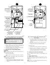
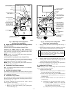
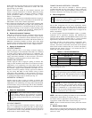
D. Pressure Switch Tubing
One collector box pressure tube (pink label) is factory connected to
the pressure switch for use when furnace is installed in UPFLOW
or HORIZONTAL LEFT applications. This tube MUST be dis-
connected and used for the condensate trap relief port tube. The
other collector box pressure tube (green label) which was factory
connected to the condensate trap relief port connection MUST be
connected to the pressure switch in DOWNFLOW or HORIZON-
TAL RIGHT applications.
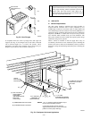
NOTE: See Fig. 13 or tube routing label on main furnace door to
check for proper connections.
Relocate tubes as described below.
1. Disconnect collector box pressure tube (pink label) attached
to pressure switch.
2. Extend collector box pressure tube (green label) which was
previously connected to condensate trap relief port connec-
tion by splicing to small diameter tube (factory-supplied in
loose parts bag).
3. Connect collector box pressure tube (green label) to pres-
sure switch connection labeled COLLECTOR BOX.
4. Use remaining small diameter tube (factory-supplied in
loose parts bag) to extend collector box pressure tube (pink
label) which was previously connected to pressure switch.
5. Route this extended tube (pink label) to condensate trap
relief port connection.
6. Determine appropriate length, cut, and connect tube.
7. Clamp tube to relief port connection.
E. Condensate Trap Freeze Protection
Refer to Condensate Drain Protection section for recommenda-
tions and procedures.
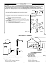
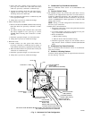
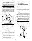
F. Construct a Working Platform
Construct working platform where all required furnace clearances
are met. (See Fig. 3 and 12.)
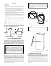
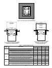
CAUTION: The condensate trap MUST be installed
below furnace. See Fig. 4 for dimensions. The drain
connection to condensate trap must also be properly
sloped to an open drain.
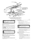
NOTE: Combustion-air and vent pipes are restricted to a mini-
mum length of 5 ft. (See Table 7.)
NOTE: A 12-in. minimum offset pipe section is recommended
with short (5 to 8 ft) vent systems. This recommendation is to
reduce excessive condensate droplets from exiting the vent pipe.
(See Fig. 12 or 35.)
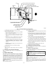
→ Fig. 13—Horizontal Right Tube Configuration
A02289
PLUG
COLLECTOR BOX DRAIN TUBE
(BLUE AND WHITE STRIPED)
INDUCER HOUSING
DRAIN TUBE (VIOLET)
COLLECTOR BOX
EXTENSION TUBE
COLLECTOR BOX TUBE (GREEN)
CAP
COLLECTOR BOX DRAIN TUBE (BLUE)
COLLECTOR BOX TUBE (PINK)
AUXILIARY "J" BOX RELOCATED HERE
CONDENSATE
TRAP
—12—