


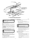
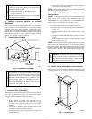
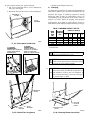
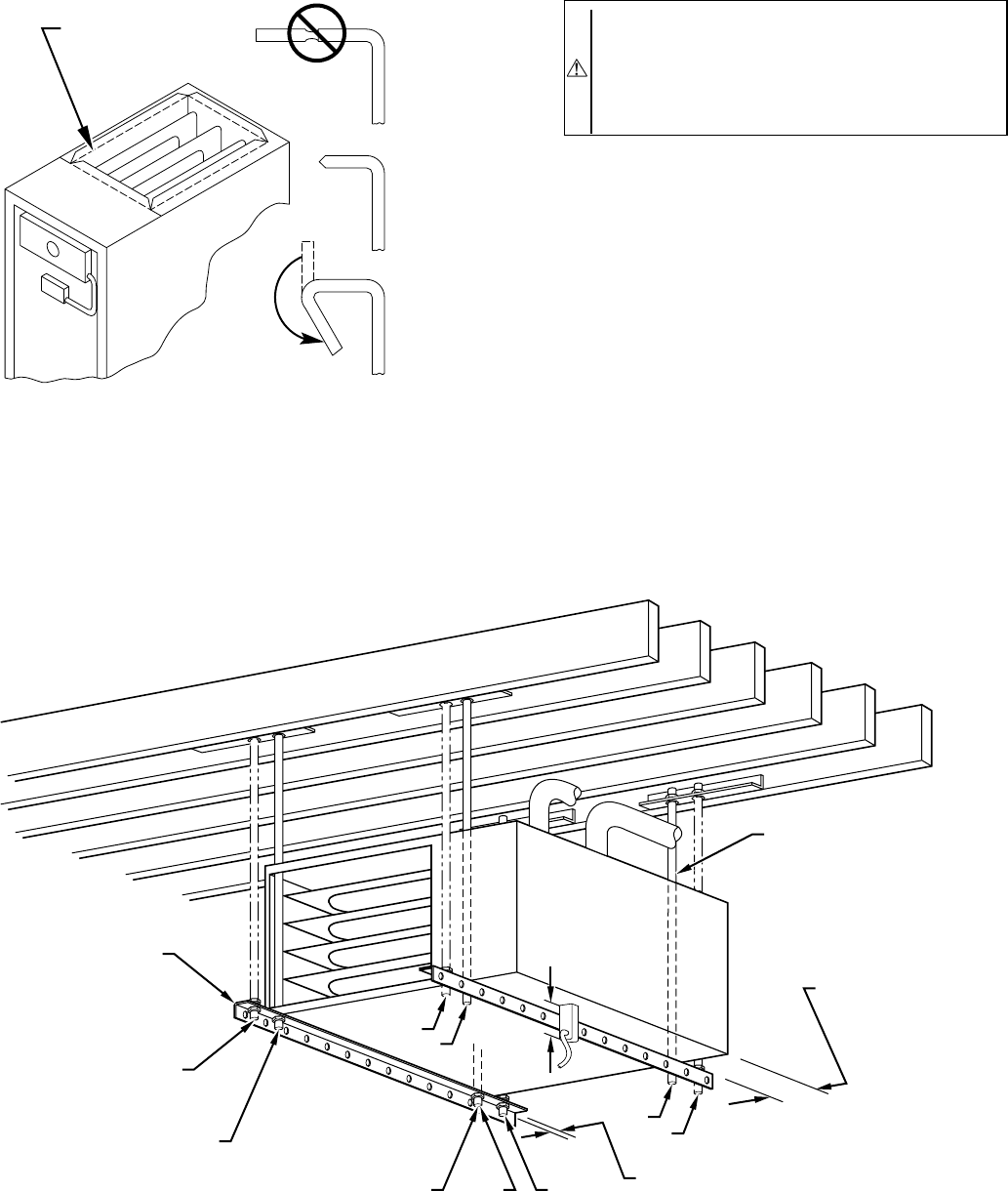
be suspended from each corner by hanger bolts and angle iron
supports. (See Fig. 23.) Cut hanger bolts (4 each 3/8-in. all-thread
rod) to desired length. Use 1 X 3/8-in. flat washers, 3/8-in.
lockwashers, and 3/8-in. nuts on hanger rods as shown in Fig. 23.
Dimples are provided for hole locations. (See Fig. 2.)
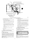
CAUTION: The entire length of furnace MUST be
supported when furnace is used in a horizontal position to
ensure proper draining. When suspended, bottom brace
supports sides and center blower shelf. When unit is
supported from the ground, blocks or pad should support
sides and center blower shelf area.
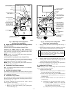
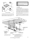
IV. AIR DUCTS
A. General Requirements
The duct system should be designed and sized according to
accepted national standards such as those published by: Air
Conditioning Contractors Association (ACCA), Sheet Metal and
Air Conditioning Contractors National Association (SMACNA) or
American Society of Heating, Refrigerating and Air Conditioning
Engineers (ASHRAE) or consult The Air Systems Design Guide-
lines reference tables available from your local distributor. The
duct system should be sized to handle the required system design
CFM at the design static pressure.
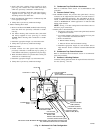
When a furnace is installed so that the supply ducts carry air
circulated by the furnace to areas outside the space containing the
furnace, the return air must also be handled by a duct(s) sealed to
the furnace casing and terminating outside the space containing the
furnace.
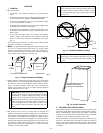
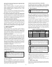
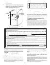
Fig. 22—Duct Flanges
A93029
NO
YES
YES
PERFORATED
DISCHARGE DUCT
FLANGE
210°
MIN
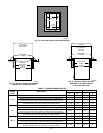
Fig. 23—Crawlspace Horizontal Application
A93304
NOTES:
ANGLE
IRON OR
EQUIVALENT
(B)
(A) ROD LOCATION
USING DIMPLE
LOCATORS
(SEE DIMENSIONAL
DWG FOR
LOCATIONS)
13
/16-IN. MAX
ALTERNATE SUPPORT
LOCATION FROM BACK
ALTERNATE SUPPORT
LOCATION 4-IN. MIN
8-IN. MAX
3
⁄8-IN. ROD
(A)
(B)
(A)
(B)
(B)
(A)
1. A 1 In. clearance minimum between top of
furnace and combustible material.
2. The entire length of furnace must be
supported when furnace is used in horizontal
position to ensure proper drainage.
(A) PREFERRED ROD LOCATION
(B) ALTERNATE ROD LOCATION
DRAIN
5
3
⁄
4
″
3
/8-IN. HEX NUT
& WASHER (4)
REQD PER ROD
—16—