


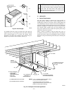
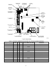
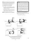
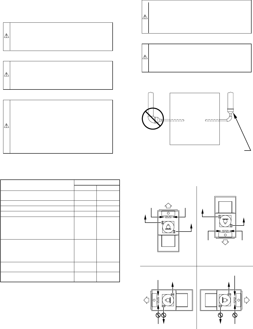
Furnace combustion-air and vent pipe connections must be at-
tached as shown in Fig. 34. Combustion-air intake plug fitting and
inducer housing alternate vent cap may need to be relocated in
some applications.
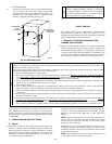
CAUTION: When combustion-air pipe is installed
above a suspended ceiling, pipe must be insulated with
3/8-in. thick Armaflex-type insulation. Combustion-air
pipe should also be insulated when it passes through a
warm, humid space.
CAUTION: When vent pipe is exposed to temperatures
below freezing, such as when it passes through an
unheated space or when a chimney is used as a raceway,
pipe must be insulated as shown in Table 8 with
Armaflex-type insulation.
CAUTION: Combustion air must not be taken from
inside structure because that air is frequently contami-
nated by halogens, which include fluorides, chlorides,
bromides, and iodides. These elements are found in
aerosols, detergents, bleaches, cleaning solvents, salts, air
fresheners, adhesives, paint, and other household prod-
ucts. Locate combustion-air inlet as far as possible from
swimming pool and swimming pool pump house.
Excessive exposure to contaminated combustion air will
result in safety and performance related problems.
WARNING: Solvent cements are combustible. Keep
away from heat, sparks, and open flame. Use only in well
ventilated areas. Avoid breathing in vapor or allowing
contact with skin or eyes. Failure to follow this warning
could result in fire, property damage, personal injury, or
death.
WARNING: All combustion-air and vent pipes must be
airtight and watertight. Pipes must also terminate exactly
as shown in Fig. 37, 38, 39, 40, or 41. Failure to follow
this warning could result in property damage, personal
injury, or death.
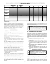
TABLE 6—COMBUSTION-AIR AND VENT PIPE
TERMINATION CLEARANCES
LOCATION
CLEARANCE (FT)
U.S.A. Canada
Above grade level or above antici-
pated snow depth
11†
Dryer/Water heater vent See Note 5 See Note 5
From plumbing vent stack 33
From any mechanical fresh air intake See Note 4 See Note 6
For furnaces with an input capacity of
100,000 Btuh or less—from any non-
mechanical air supply (windows or
doors which can be opened) or
combustion-air opening
11
For furnaces with an input capacity
greater than 100,000 Btuh —from any
non-mechanical air supply (windows
or doorswhich can be opened) or
combustion-airopening
13
From service regulator vent, electric
and gas meters, and relief equipment
See Note 6 See Note 6
Above grade when adjacent to public
walkway
See Note 3 See Note 3
† 18 in. above roof surface
NOTES:
1. If installing 2 adjacent furnaces, refer to Multiventing and Vent Terminations
section for proper vent configurations.
2. When locating combustion-air and vent terminations, consideration must be
given to prevailing winds, location, and other conditions which may cause
recirculation of the appliance’s own flue products or the flue products of
adjacent vents. Recirculation can cause poor combustion, inlet condensate
problems, and accelerated corrosion of heat exchangers.
3. Vent termination can not terminate less than 2 ft horizontal and 7 ft above
public walkway or where condensate vapor or droplets may be a hazard.
4. Vent termination must be at least 3 feet above any forced draft inlets within
10 feet horizontal. Vent termination must be at least 3 feet horizontal from
other direct vent appliances intake unless otherwise specified by manufac-
turer.
5. 3 ft radius of furnace vent air-intake terminal and 1 ft horizontally from
vertical centerline of furnace vent air-intake terminal.
6. Above a meter/regulator within 3 feet horizontally of vertical centerline of
meter/regulator vent outlet to a maximum vertical distance of 15 feet.
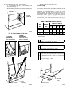
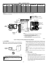
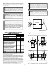
Fig. 33—Combustion-Air and Vent Pipe Diameter
Transition Location and Elbow Configuration
A93034
FURNACE
PIPE DIAMETER
TRANSITION IN
VERTICAL SECTION
NOT IN
HORIZONTAL
SECTION
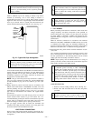
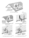
Fig. 34—Combustion-Air and Vent Pipe Connections
A96187
COMBUSTION-
AIR
COMBUSTION-
AIR
AIR
FLOW
VENT
VENT
VENT
AIR
FLOW
AIR
FLOW
AIR
FLOW
UPFLOW DOWNFLOW
HORIZONTAL-LEFT DISCHARGE HORIZONTAL-RIGHT DISCHARGE
Select 1 vent pipe connection and
1 combustion-air pipe connection.
COMBUSTION-
AIR
COMBUSTION-
AIR
COMBUSTION-
AIR
COMBUSTION-
AIR
VENT
VENT
VENT
NOTE: Select 1 vent pipe connection and
1 combustion-air pipe connection.
NOTE:
—24—