


These furnaces are shipped with the following materials to assist in
proper furnace installation. These materials are shipped in the main
blower compartment.
Installer Packet includes:
Installation, Start-Up, and Operating Instructions
Service and Maintenance Procedures
User’s Information Manual
Warranty Certificate
Loose Parts Bag includes: Quantity
Pressure tube extension 1
Collector box or condensate trap extension tube 1
Inducer housing drain tube 1
1/2-in. CPVC street elbow 2
Drain tube coupling 1
Drain tube coupling grommet 1
Vent and combustion-air pipe support 2
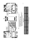
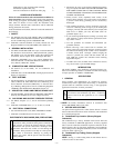
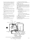
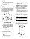
→ Fig. 3—Clearances to Combustibles
A02250
Clearance in inches.
Vent clearance to
combustibles 0".
This furnace is approved for UPFLOW, DOWNFLOW and
HORIZONTAL installations.
*
BOTTOM
0"
Ø
3"
0"
§
0"
TOP/PLENU
M
1"
0"
§
30
MIN
ALL POSITIONS:
S
I
D
E
F
R
O
N
T
B
C
K
A
S
E
R
V
I
E
C
F
R
O
N
T
S
I
D
E
U
F
R
N
A
C
E
Clearance arrows
do not change with
furnace orientation.
†
328068-201 REV. A
LIT - TOP
MINIMUM INCHES CLEARANCE TO COMBUSTIBLE CONSTRUCTION
†
HORIZONTAL POSITIONS:
DOWNFLOW POSITIONS:
§
Ø
*
Mimimum front clearance for service 30 inches (762mm).
This forced air furnace is equipped for use with natural gas at altitudes 0 - 10,000 ft (0 - 3,050m), except 140 size furnaces are only approved for altitudes 0 - 7,000 ft.
(0 - 2,135m).
An accessory kit, supplied by the manufacturer, shall be used to convert to propane gas use or may be required for some natural gas applications.
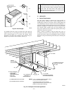
This furnace is for indoor installation in a building constructed on site. This furnace may be installed in a manufactured (mobile) home when stated on rating plate and
using factory authorized kit.
This furnace may be installed on combustible flooring in alcove or closet at
Minimum Inches Clearance To Combustible Construction
as described below.
This furnace requires a special venting system. Refer to the installation instructions for parts list and method of installation. This furnace is for use with schedule-40 PVC,
PVC-DWV, CPVC, or ABS-DWV pipe, and must not be vented in common with other gas-fired appliances. Construction through which vent/air intake pipes may be
installed is maximum 24 inches (600 mm), minimum 3/4 inches (19 mm) thickness (including roofing materials).
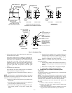
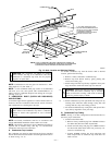
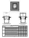
UPFLOW OR
DOWNFLOW
1/2" MAX
LEVEL (0")
TO
For upflow and downflow applications, furnace must be installed level, or pitched within 1/2" of level. For a
horizontal application, the furnace must be pitched minimum 1/4" to maximum of 1/2" forward for proper
drainage. See Installation Manual for IMPORTANT unit support details on horizontal applications.
HORIZONTAL
MIN 1/4" TO 1/2" MAX
For installation on combustible floors only when installed on special base No.
KGASB0201ALL, Coil Assembly, Part No. CD5 or CK5, or Coil Casing, Part No. KCAKC.
Line contact is permissible only between lines formed by intersections of top and two sides
of furnace jacket, and building joists, studs, or framing.
Clearance shown is for air inlet and air outlet ends.
120 size furnace requires 1 inch bottom clearance to combustible materials.
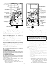
FRONT
FRONT
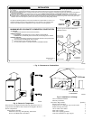
INSTALLATION
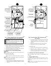
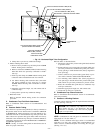
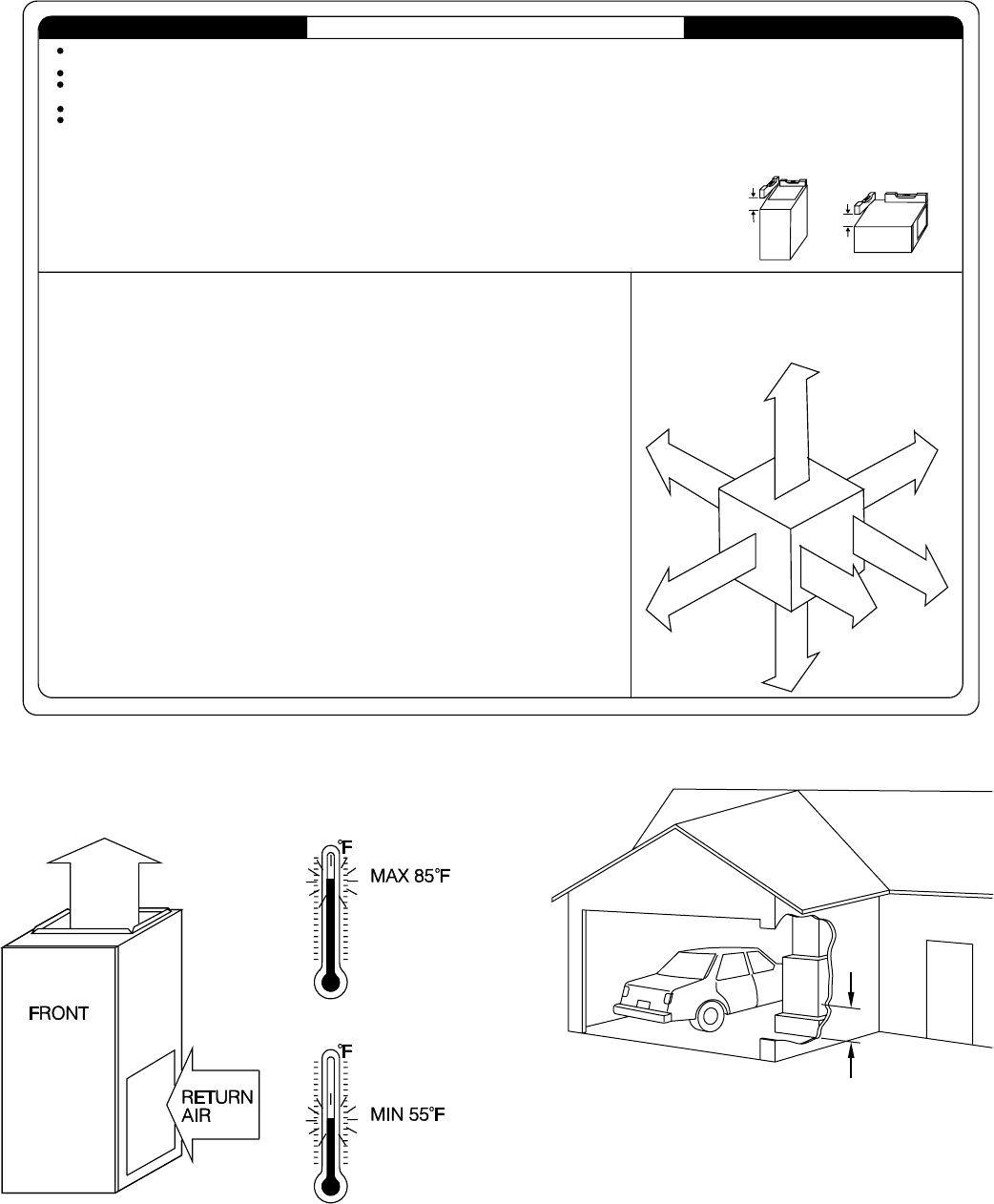
Fig. 4—Return-Air Temperature
A93042
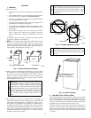
Fig. 5—Installation in a Garage
A93044
18-IN. MINIMUM
TO BURNERS
—4—