


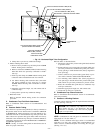
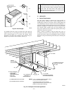
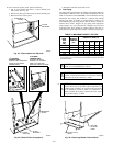
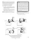
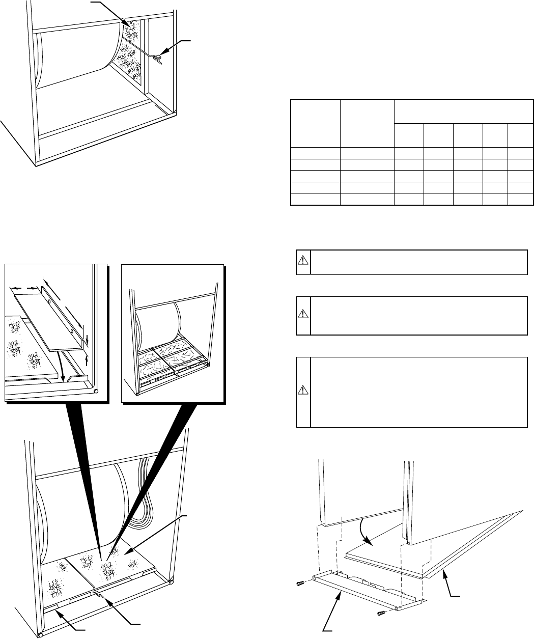
To remove bottom closure panel, perform following:
1. Tilt or raise furnace and remove 2 screws holding front
filler panel. (See Fig. 26.)
2. Rotate front filler panel downward to release holding tabs.
3. Remove bottom closure panel.
4. Reinstall front filler panel and screws.
G. Gas Piping
Gas piping must be installed in accordance with national and local
codes. Refer to NFGC in the U.S. Canadian installations must be
made in accordance with NSCNGPIC and all authorities having
jurisdiction. Gas supply line should be a separate line running
directly from meter to furnace, if possible. Refer to Table 3 for
recommended gas pipe sizing. Risers must be used to connect to
furnace and to meter. Support all gas piping with appropriate
straps, hangers, etc. Use a minimum of 1 hanger every 6 ft. Joint
compound (pipe dope) should be applied sparingly and only to
male threads of joints. Pipe dope must be resistant to propane gas.
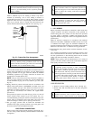
CAUTION: Connect gas pipe to furnace using a backup
wrench to avoid damaging gas controls.
WARNING: Gas valve shutoff switch MUST be facing
forward or tilted upward. Failure to follow this warning
could result in property damage or death.
WARNING: Never purge a gas line into a combustion
chamber. Never test for gas leaks with an open flame. Use
a commercially available soap solution made specifically
for the detection of leaks to check all connections. A
failure to follow this warning could result in fire, explo-
sion, personal injury, or death.
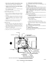
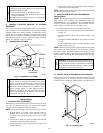
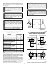
Fig. 24—Filter Installed for Side Inlet
A93045
FILTER
RETAINER
WASHABLE
FILTER
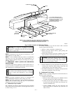
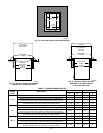
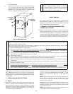
Fig. 25—Bottom Filter Arrangement
A00290
WASHABLE
FILTER
FILTER
SUPPORT
FILTER
RETAINER
17
1
⁄2-IN. WIDE
CASINGS ONLY:
INSTALL FIELD-SUPPLIED
FILTER FILLER STRIP
UNDER FILTER.
1″
24
1
/
2
″
3″
21-IN. WIDE
CASINGS ONLY:
SUPPORT RODS (3)
EXTEND 1/4" ON EACH
SIDE OF FILTER AND
REST ON CASING FLANGE
Fig. 26—Removing Bottom Closure Panel
A93047
BOTTOM
CLOSURE
PANEL
FRONT FILLER
PANEL
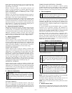
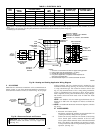
TABLE 3—MAXIMUM CAPACITY OF PIPE*
NOMINAL
IRON
PIPE
SIZE
(IN.)
INTERNAL
DIAMETER
(IN.)
LENGTH OF PIPE (FT)
10 20 30 40 50
1/2 0.622 175 120 97 82 73
3/4 0.824 360 250 200 170 151
1 1.049 680 465 375 320 285
1-1/4 1.380 1400 950 770 660 580
1-1/2 1.610 2100 1460 1180 990 900
* Cubic ft of gas per hr for gas pressures of 0.5 psig (14-in. wc) or less, and a
pressure drop of 0.5-in. wc (based on a 0.60 specific gravity gas). Ref: Table
9-2 NFPA 54-2002.
—18—
→