


e. Find closest natural gas heat value and specific gravity in
Table 11.
f. Follow heat value and specific gravity lines to point of
intersection to find orifice size and low- and high-heat
manifold pressure settings for proper operation.
EXAMPLE: (0—2000 ft altitude)
Heating value = 1050 Btu/cu ft
Specific gravity = 0.62
Therefore: Orifice No. 45
Manifold pressure: 3.8-in. wc for high heat
1.6-in. wc for low heat
* Furnace is shipped with No. 45 orifices. In this example,
all main burner orifices are the correct size and do not need
to be changed to obtain proper input rate.
g. Check and verify burner orifice size in furnace. NEVER
ASSUME ORIFICE SIZE; ALWAYS CHECK AND
VERIFY.
2. Adjust manifold pressure to obtain input rate.
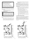
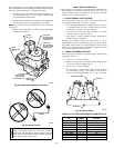
a. Remove burner enclosure front.
NOTE: Manifold pressure MUST always be measured with the
burner box cover REMOVED.
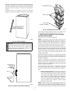
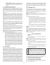
b. Remove regulator seal caps that conceal adjustment
screws for low- and high-heat gas valve regulators. (See
Fig. 62.)
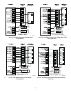
c. Turn setup switch SW1-2 on control center to ON
position. (See Fig. 32.) This keeps furnace locked in
low-heat operation.
d. Jumper R and W/W1 thermostat connections on furnace
control to start furnace.
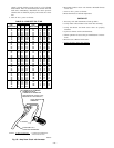
e. Turn low-heat adjusting screw (3/32 hex Allen wrench)
counterclockwise (out) to decrease input rate or clock-
wise (in) to increase input rate.
NOTE: DO NOT set low-heat manifold pressure less than 1.3-in.
wc or more than 1.7-in. wc for natural gas. If manifold pressure is
outside this range, change main burner orifices to obtain manifold
pressure in this range.
CAUTION: DO NOT bottom-out gas valve regulator
adjusting screw. This can result in unregulated manifold
pressure and result in excess overfire and heat exchanger
failures.
NOTE: If orifice hole appears damaged or it is suspected to have
been redrilled, check orifice hole with a numbered drill bit of
correct size. Never redrill an orifice. A burr-free and squarely
aligned orifice hole is essential for proper flame characteristics.
f. Turn setup switch SW1-2 to OFF position after complet-
ing low-heat adjustment.
A02335
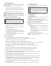
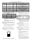
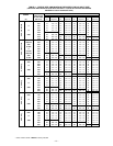
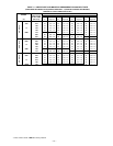
→ Fig. 58—A/C or CF Airflow Selection Chart
Based on 350CFM/Ton
AIR CONDITIONING AIRFLOW 040,060 & 042080
MODEL
060080 & 100
MODEL
120 MODEL
TONS (12,000 BTU/HR) (CFM)
1-1/2 525 X
X
2 700 X X X
2-1/2 875 X X X
3 1050 X X X
3-1/2 1225 X X X
4 1400 X X
5 1750 X
6 2100 X
X-INDICATES AN ALLOWABLE SELECTION.
A/C OR CF AIRFLOW SELECTION CHART
BASED ON 350 CFM/TON
MODEL
SIZE
040, 060,
042080
DEF 525
2
700 875 1050
1
1225 1225 1225
060080, 100 DEF 700 875 1050 1225 1400 1750
1
1750
120 DEF 700 875
2
1050 1225 1400 1750
1
2100
1.DEFAULT A/C AIRFLOW WHEN A/C SWITCHES ARE IN OFF POSITION
2.DEFAULT CONT. FAN AIRFLOW WHEN CF SWITCHES ARE IN OFF POSITION
2
—40—