


WARNING: Use proper length of pipe to avoid stress on
gas control manifold. Failure to follow this warning could
result in a gas leak resulting in fire, explosion, personal
injury, or death.
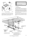
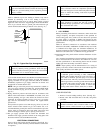
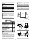
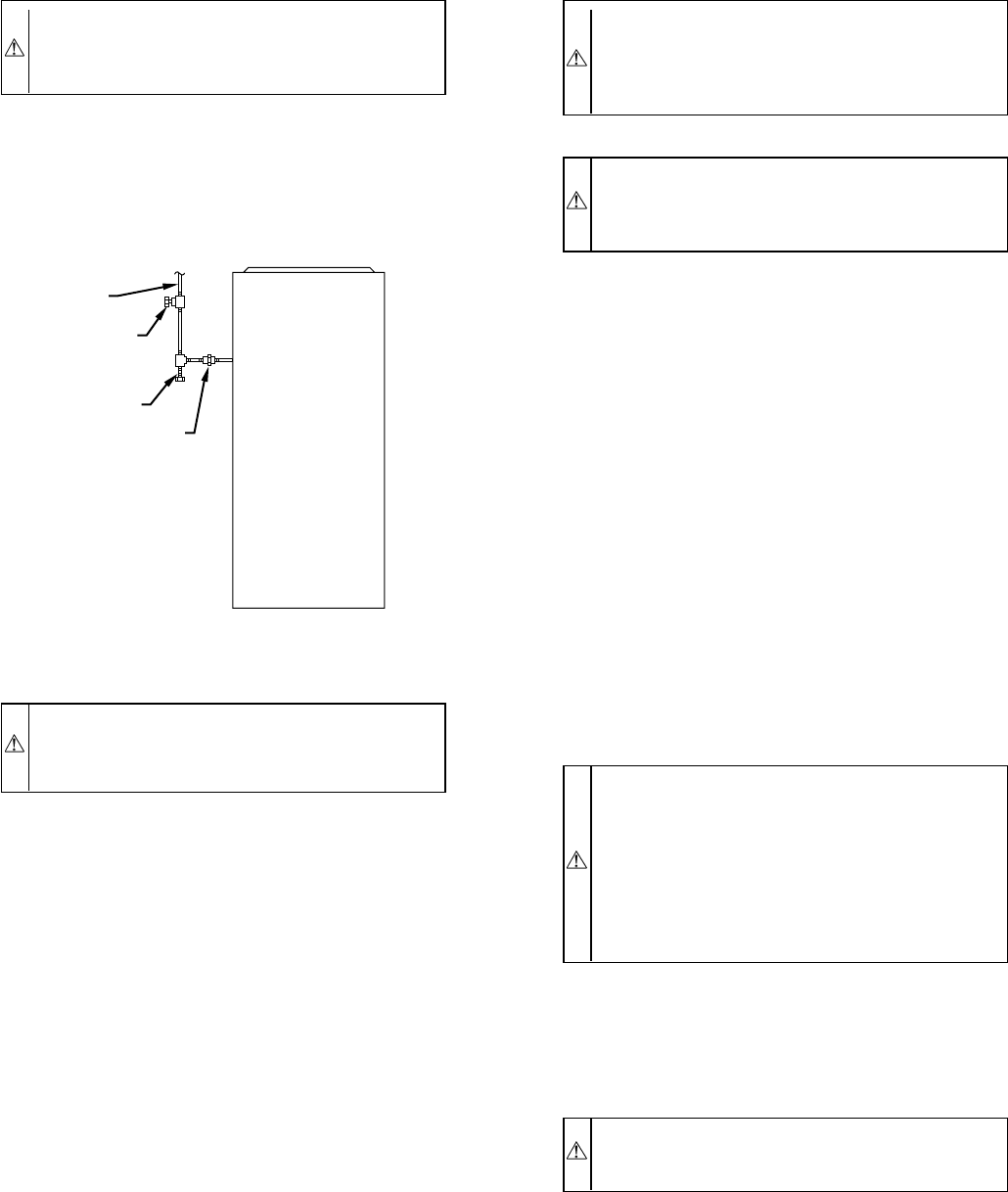
Install a sediment trap in riser leading to furnace. Trap can be
installed by connecting a tee to riser leading to furnace so
straight-through section of tee is vertical. Then connect a capped
nipple into lower end of tee. Capped nipple should extend below
level of gas controls. Place a ground joint union between gas
control manifold and manual gas shutoff valve. (See Fig. 27.)
CAUTION: If a flexible connector is required or al-
lowed by authority having jurisdiction, black iron pipe
shall be installed at furnace gas control valve and extend
a minimum of 2 in. outside furnace casing.
An accessible manual shutoff valve MUST be installed external to
furnace casing and within 6 ft of furnace. A 1/8-in. NPT plugged
tapping, accessible for test gage connection, MUST be installed
immediately upstream of gas supply connection to furnace and
downstream of manual shutoff valve.
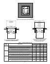
NOTE: The gas valve inlet pressure tap connection is suitable to
use as test gage connection providing test pressure DOES NOT
exceed maximum 0.5 psig (14-in. wc) stated on gas valve. (See
Fig. 62.)
Piping should be pressure and leak tested in accordance with
NFGC in the United States or NSCNGPIC in Canada, local, and
national plumbing and gas codes before the furnace has been
connected. If pressure exceeds 0.5 psig (14-in. wc), gas supply
pipe must be disconnected from furnace and capped before
pressure test.
If test pressure is equal to or less than 0.5 psig (14-in. wc), turn off
electric shutoff switch located on gas valve before test. It is
recommended that ground joint union be loosened before pressure
testing. After all connections have been made, purge lines and
check for leakage at furnace prior to placing it into service.
The gas supply pressure shall be within the maximum and
minimum inlet supply pressures marked on the rating plate with
the furnace burners ON at HI-HEAT and OFF.
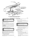
ELECTRICAL CONNECTIONS
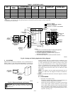
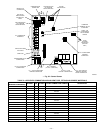
See Fig. 28 for field wiring diagram showing typical field 115-v
and 24-v wiring. Check all factory and field electrical connections
for tightness.
WARNING: Blower access door switch opens 115-v
power to furnace control. No component operation can
occur. Do not bypass or close switch with panel removed.
Failure to follow this warning could result in personal
injury or death.
CAUTION: Furnace control must be grounded for
proper operation or control will lock out. Control is
grounded through green/yellow wire connected to gas
valve and burner box screw.
I. 115-V WIRING
Before proceeding with electrical connections, make certain that
voltage, frequency, and phase correspond to that specified on
furnace rating plate. Also, check to be sure that service provided
by power supply is sufficient to handle load imposed by this
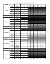
equipment. Refer to rating plate or Table 4 for equipment electrical
specifications.
Make all electrical connections in accordance with National
Electrical Code (NEC) ANSI/NFPA 70-2002 and any local codes
or ordinances that might apply. For Canadian installations, all
electrical connections must be made in accordance with Canadian
Electrical Code CSA C22.1 or authorities having jurisdiction.
Field-supplied wiring shall conform with the limitations of 63°F
(33°C) rise.
Use a separate, branch electrical circuit containing a properly sized
fuse or circuit breaker for this furnace. See Table 4 for wire size
and fuse specifications. A disconnecting means must be located
within sight from and readily accessible to furnace.
NOTE: Proper polarity must be maintained for 115-v wiring. If
polarity is incorrect, furnace control status code indicator light will
flash rapidly and furnace will NOT operate.
WARNING: The cabinet MUST have an uninterrupted
or unbroken ground according to NEC ANSI/NFPA
70-2002 and Canadian Electrical Code CSA C22.1 or
local codes to minimize personal injury if an electrical
fault should occur. This may consist of electrical wire or
conduit approved for electrical ground when installed in
accordance with existing electrical codes. Do not use gas
piping as an electrical ground. Failure to follow this
warning could result in electric shock, fire, or death.
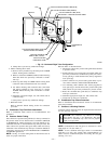
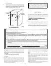
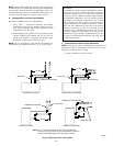
J-BOX RELOCATION
1. Remove 2 screws holding auxiliary J-box. (See Fig. 30.)
2. Rotate J-box 180° and attach box to left side, using holes
provided.
CAUTION: If manual disconnect switch is to be
mounted on furnace, select a location where a drill or
fastener will not contact electrical or gas components.
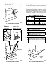
Fig. 27—Typical Gas Pipe Arrangement
A93324
UNION
SEDIMENT
TRAP
MANUAL
SHUTOFF
VALVE
(REQUIRED)
GAS
SUPPLY
—19—
→
→
→