


low-heat pressure switch LPS closes. When the high-heat pressure
switch closes, inducer motor RPM is noted by the furnace control
CPU before the 25-sec prepurge period begins. The RPM is used
to evaluate vent system resistance. This evaluation is then used to
determine the required RPM necessary to operate the inducer
motor in high-heat mode.
2. Ignitor Warm-Up-At end of the prepurge period, the Hot
Surface Igniter HSI is energized for a 17-sec igniter
warm-up period.
3. Trial-For-Ignition Sequence-When the igniter warm-up
period is completed the main gas valve relay contacts GVR
closes to energize the gas valve solenoid GV-M. The gas
valve solenoid GV-M permits gas flow to the burners where
it is ignited. After 5 seconds, the igniter HSI is de-energized
and a 2-second Flame-Proving period begins.
If the furnace control CPU selects high-heat operation, the
high-heat gas valve solenoid GV-HI is also energized.
4. Flame-Proving-When burner flame is proved at the flame-
proving sensor electrode FSE, the furnace control CPU
begins the blower-ON delay period and continues to hold
the gas valve GV-M open. If the burner flame is not proved
within two seconds, the control CPU will close the gas
valve GV-M, and the furnace control CPU will repeat the
ignition sequence for up to three more Trials-For-Ignition
before going to Ignition-Lockout. Lockout will be reset
automatically after three hours, by momentarily interrupting
115 vac power to the furnace, or by interrupting 24 vac
power at SEC1 or SEC2 to the furnace control CPU (not at
W/W1, G, R, etc.).
If flame is proved when flame should not be present, the
furnace control CPU will lock out of Gas-Heating mode and
operate the inducer motor IDM on high speed until flame is
no longer proved.
5. Inducer Speed Change-If the cycle starts in low-heat, the
furnace control CPU reduces the inducer speed slightly after
flame sense. If cycle starts in high-heat, the furnace control
CPU increases the inducer speed 15 seconds after flame
sense. The reduction in speed in low-heat is to optimize
combustion for maximum efficiency.
6. Blower-On delay-If the burner flame is proven, the
blower-ON delay for low-heat and high-heat are as follows:
Low-heat-60 seconds after the gas valve GV-M is opened,
the BLWM is turned ON at low-heat airflow.
High-heat-35 seconds after gas valve GV-M is opened, the
BLWM is turned ON at high-heat airflow.
Simultaneously, the humidifier terminal HUM and elec-
tronic air cleaner terminal EAC-1 are energized and remain
energized throughout the heating cycle.
7. Switching From Low- To High- Heat- If the furnace
control CPU switches from low-heat to high-heat, the
furnace control CPU will de-energize the the high-heat
pressure switch relay HPSR to close the NC contact and
slowly increase the inducer motor speed until the high-heat
pressure switch HPS closes. When the high-heat pressure
switch HPS closes, the high-heat gas valve solenoid GV-HI
is energized and the inducer motor RPM is noted by the
furnace control CPU. The RPM is used to evaluate vent
system resistance. This evaluation is then used to determine
the required RPM necessary to operate the inducer motor in
high-heat mode. The blower motor BLWM will transition
to high-heat airflow five seconds after the furnace control
CPU switches from low-heat to high-heat.
8. Switching From High- To Low- Heat-The furnace control
CPU will not switch from high-heat to low-heat while the
thermostat R-to-W circuit is closed when using a single-
stage thermostat.
9. Blower-Off delay- When the thermostat is satisfied, the R
to W circuit is opened, de-energizing the gas valve GV-M,
stopping gas flow to the burners, and de-energizing the
humidifier terminal HUM. The inducer motor IDM will
remain energized for a 15-second post-purge period. The
blower motor BLWM and air cleaner terminal EAC-1 will
remain energized at low-heat airflow or transition to low-
heat airflow for 90, 120, 150, or 180 seconds (depending on
selection at blower-OFF delay switches). The furnace
control CPU is factory-set for a 120-second blower-OFF
delay.
II. TWO-STAGE THERMOSTAT AND TWO-STAGE
HEATING
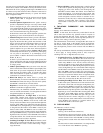
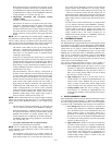
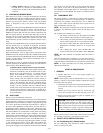
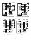
See Fig. 56 for thermostat connections
NOTE: In this mode, the low-heat only switch SW1-2 must be
ON to select the low-heat only operation mode in response to
closing the thermostat R-to-W1 circuit. Closing the thermostat
R-to-W1-and-W2 circuits always causes high-heat operation, re-
gardless of the setting of the low-heat-only switch.
The wall thermostat ″calls for heat″, closing the R to W1 circuit for
low-heat or closing the R to W1-and-W2 circuits for high-heat.
The furnace control performs a self-check and verifies the low-
heat and high-heat pressure switch contacts LPS and HPS are
open.
The start-up and shutdown functions and delays described in item
1. above apply to 2-stage heating mode as well, except for
switching from low- to high-heat and vice versa.
1. Switching From Low- To High- Heat-If the thermostat R
to W1 circuit is closed and the R to W2 circuit closes, the
furnace control CPU will de-energize the high-heat pressure
switch relay HPSR to close the NC contact and slowly
increase the inducer motor speed until the high-heat pres-
sure switch HPS closes. When the high-heat pressure switch
closes, the high-heat gas valve solenoid GV-HI is energized
and the inducer motor RPM is noted by the furnace control
CPU. The RPM is used to evaluate vent system resistance.
This evaluation is then used to determine the required RPM
necessary to operate the inducer motor in high-heat mode.
The blower motor BLWM will transition to high-heat
airflow five seconds after the R to W2 circuit closes.
2. Switching From High- To Low- Heat- If the thermostat R
to W2 circuit opens, and the R to W1 circuit remains closed,
the furnace control CPU will energize the high-heat pres-
sure switch relay HPSR to open the NC contact and slowly
decrease the inducer motor speed to the required low-heat
RPM. When the high-heat pressure switch HPS opens, the
high-heat gas valve solenoid GV-HI is de-energized. When
the inducer motor IDM reduces pressure sufficiently, the
high-heat pressure switch HPS will open. The gas valve
solenoid GV-M will remain energized as long as the
low-heat pressure switch LPS remains closed. The blower
motor BLWM will transition to low-heat airflow five
seconds after the R to W2 circuit opens.
III. COOLING MODE
The thermostat “calls for cooling”
1. Single-Speed Cooling
(See Fig. 28 for thermostat connections.)
The thermostat closes R-to-G-and-Y circuits. The R-to-Y
circuit starts the outdoor unit, and R-to-G-and-Y/Y2 circuits
start the furnace blower motor BLWM on cooling airflow.
Cooling airflow is based on the A/C selection shown in Fig.
58.
The electronic air cleaner terminal EAC-1 is energized with
115-v when blower motor BLWM is operating.
—34—