


C. Condensate Trap Field Drain Attachment
Refer to Condensate Drain section for recommendations and
procedures.
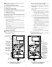
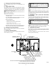
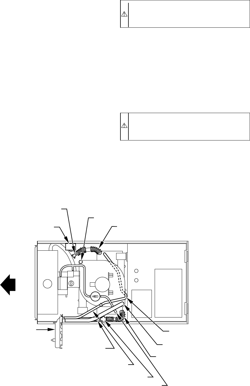
D. Pressure Switch Tubing
The LOWER collector box pressure tube (pink label) is factory
connected to the pressure switch for use when furnace is installed
in UPFLOW applications. This tube MUST be disconnected,
extended, rerouted, and then reconnected to the pressure switch in
HORIZONTAL LEFT applications.
NOTE: See Fig. 9 or tube routing label on main furnace door to
check for proper connections.
Modify tube as described below.
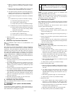
1. Disconnect collector box pressure tube (pink label) attached
to pressure switch.
2. Use smaller diameter tube (factory-supplied in loose parts
bag) to extend tube disconnected in item 1.
3. Route extended tube:
a. Behind inducer housing.
b. Between blower shelf and inducer housing.
c. Behind inducer motor bracket.
d. Between inducer motor and pressure switch.
4. Determine appropriate length, cut, and reconnect tube to
pressure switch connection labeled COLLECTOR BOX.
E. Condensate Trap Freeze Protection
Refer to Condensate Drain Protection section for recommenda-
tions and procedures.
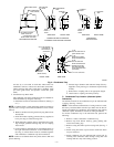
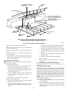
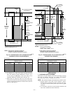
F. Construct a Working Platform
Construct working platform where all required furnace clearances
are met. (See Fig. 3 and 10.)
CAUTION: The condensate trap MUST be installed
below furnace. See Fig. 4 for dimensions. The drain
connection to condensate trap must also be properly
sloped to an open drain.
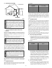
NOTE: Vent pipe length is restricted to a minimum of 5 ft. (See
Table 4.)
NOTE: A 12-in. minimum horizontal pipe section is recom-
mended with short (5 to 8 ft) vent systems. This recommendation
is to reduce excessive condensate droplets from exiting the vent
pipe. (See Fig. 10 or 32.)
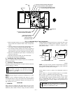
V. HORIZONTAL RIGHT (SUPPLY-AIR DISCHARGE)
APPLICATIONS
A horizontal right furnace application is where furnace blower is
located to the left of combustion and controls section of furnace,
and conditioned air is discharged to the right.
CAUTION: Local codes may require a drain pan under
entire furnace and condensate trap when a condensing
furnace is used in attic application or over a finished
ceiling.
NOTE: In Canada, installations shall be in accordance with
current NSCNGPIC Installation Codes and/or local codes.
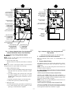
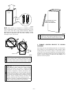
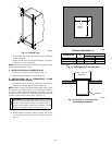
A. Condensate Trap Location
The condensate trap must be removed from the factory-installed
blower shelf location and relocated in selected application location
as shown in Fig. 2 or 11.
To relocate condensate trap from the blower shelf to desired
location, perform the following:
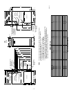
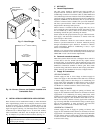
Fig. 9—Horizontal Left Tube Configuration
A93302
CONDENSATE
TRAP
AUXILIARY "J" BOX
RELOCATED HERE
PLUG
CAP
INDUCER HOUSING
DRAIN TUBE (VIOLET)
COLLECTOR BOX
DRAIN TUBE (BLUE)
COLLECTOR BOX TUBE (PINK)
RELOCATE TUBE BETWEEN BLOWER SHELF AND INDUCER HOUSING FOR
040, 060, AND 080 HEATING INPUT FURNACES
COLLECTOR BOX
EXTENSION TUBE
COLLECTOR BOX
DRAIN TUBE
(BLUE AND WHITE STRIPED)
DRAIN TUBE COUPLING
COLLECTOR BOX
TUBE (GREEN)
COLLECTOR
BOX EXTENSION
DRAIN TUBE
—9—