


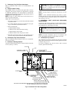
D. Return Air Connections
1. Upflow Furnaces
The return-air duct must be connected to bottom, sides (left or
right), or a combination of bottom and side(s) of main furnace
casing as shown in Fig. 1. Bypass humidifier may be attached into
unused side return air portion of the furnace casing. DO NOT
connect any portion of return-air duct to back of furnace casing.
2. Downflow and Horizontal Furnaces
The return-air duct must be connected to return-air opening
provided as shown in Fig. 1. DO NOT cut into casing sides or back
to attach any portion of return-air duct. Bypass humidifier connec-
tions should be made at ductwork or coil casing sides exterior to
furnace.
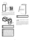
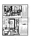
VI. FILTER ARRANGEMENT
CAUTION: Never operate unit without a filter or with
blower access panel removed.
Factory-supplied washable framed filters are shipped in blower
compartment. Determine location for filter and relocate filter
retaining wire if necessary. See Table 1 to determine correct filter
size for desired filter location. Table 1 indicates filter size,
location, and quantity shipped with this furnace. See Fig. 2 for
location and size of bottom and side return-air openings.
CAUTION: Air delivery above 1800 CFM requires that
both sides, a combination of 1 side and bottom, or bottom
only of furnace be used for return air.
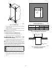
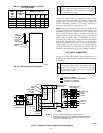
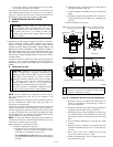
NOTE: Side return-air openings can ONLY be used in UPFLOW
configurations. Install filter(s) as shown in Fig. 20.
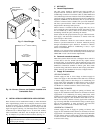
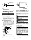
Bottom return-air opening may be used with all 4 orientations.
Filter may need to be cut to fit some furnace widths. Install filter
as shown in Fig. 21.
NOTE: Remove and discard bottom closure panel when bottom
inlet is used.
VII. BOTTOM CLOSURE PANEL
These furnaces are shipped with bottom enclosure panel installed
in bottom return-air opening. This panel MUST be in place when
side return air is used.
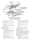
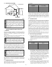
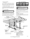
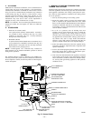
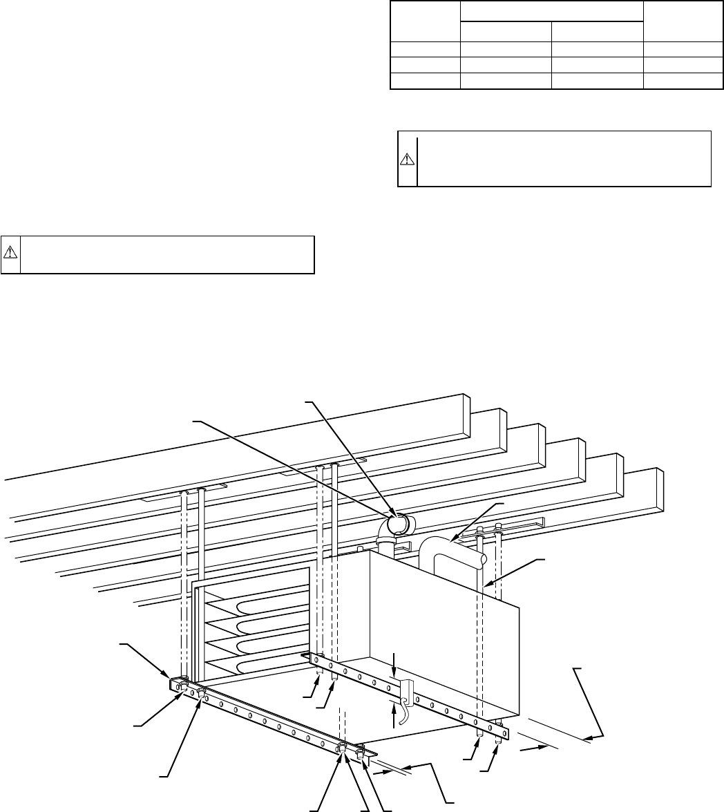
Fig. 19—Crawlspace Horizontal Application
A96209
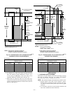
NOTES:
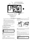
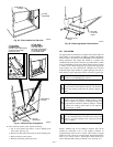
ANGLE
IRON OR
EQUIVALENT
(B)
(A) ROD LOCATION
USING DIMPLE
LOCATORS
(SEE DIMENSIONAL
DWG FOR
LOCATIONS)
13
/16-IN. MAX
ALTERNATE SUPPORT
LOCATION FROM BACK
ALTERNATE SUPPORT
LOCATION 4-IN. MIN
8-IN. MAX
A 3-IN. MINIMUM
CLEARANCE TO
COMBUSTION-AIR INTAKE
IS REQUIRED.
3
⁄8-IN. ROD
(A)
(B)
(A)
(B)
(B)
(A)
1. A 1 In. clearance minimum between top of
furnace and combustible material.
2. The entire length of furnace must be
supported when furnace is used in
horizontal position to ensure proper
drainage.
3. Bottom side combustion-air entry cannot
be used when furnace is installed with
hangers as shown.
(A) PREFERRED ROD LOCATION
(B) ALTERNATE ROD LOCATION
DRAIN
5
3
⁄
4
″
3
/8-IN. HEX NUT
& WASHER (4)
REQD PER ROD
VENT
COMBUSTION-AIR
INTAKE
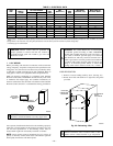
TABLE 1—FILTER INFORMATION
FURNACE
CASING
WIDTH (IN.)
FILTER SIZE (IN.)*
FILTER TYPE
FRAMED
Side Return Bottom Return
17-1/2 (1) 16 X 25 X 1† (1) 16 X 25 X 1 Cleanable
21 (1) 16 X 25 X 1 (1) 20 X 25 X 1† Cleanable
24-1/2 (2) 16 X 25 X 1† (1) 24 X 25 X 1 Cleanable
* Filters can be field modified by cutting frame as marked and folding to
desired size. Alternate sizes can be ordered from your distributor or dealer.
† Factory-provided with furnace.
—17—