


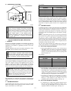
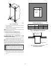
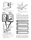
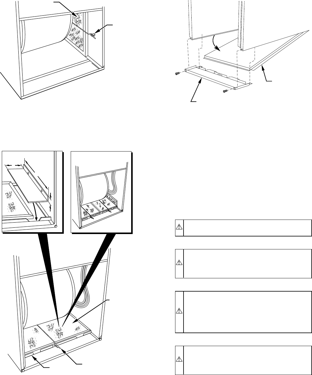
To remove bottom closure panel, perform following:
1. Tilt or raise furnace and remove 2 screws holding front
filler panel. (See Fig. 22.)
2. Rotate front filler panel downward to release holding tabs.
3. Remove bottom closure panel.
4. Reinstall front filler panel and screws.
VIII. GAS PIPING
Gas piping must be installed in accordance with national and local
codes. Refer to current edition of NFGC. Canadian installations
must be made in accordance with NSCNGPIC and all authorities
having jurisdiction. Gas supply line should be a separate line
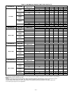
running directly from meter to furnace, if possible. Refer to Table
2 for recommended gas pipe sizing. Risers must be used to connect
to furnace and to meter. Support all gas piping with appropriate
straps, hangers, etc. Use a minimum of 1 hanger every 6 ft. Joint
compound (pipe dope) should be applied sparingly and only to
male threads of joints. Pipe dope must be resistant to propane gas.
CAUTION: Connect gas pipe to furnace using a backup
wrench to avoid damaging gas controls.
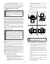
WARNING: Gas valve ON and OFF switch MUST be
facing forward or tilted upward. (See Fig. 40.) Failure to
follow this warning could result in property damage or
death.
WARNING: Never purge a gas line into a combustion
chamber. Never use matches, candles, flame, or other
sources of ignition for purpose of checking leakage. Use
a soap-and-water solution to check for leakage. A failure
to follow this warning could result in fire, explosion,
personal injury, or death.
WARNING: Use proper length of pipe to avoid stress on
gas control manifold. Failure to follow this warning could
result in a gas leak resulting in fire, explosion, personal
injury, or death.
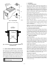
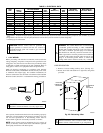
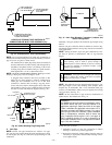
Install a sediment trap in riser leading to furnace. Trap can be
installed by connecting a tee to riser leading to furnace so
straight-through section of tee is vertical. Then connect a capped
nipple into lower end of tee. Capped nipple should extend below
level of gas controls. Place a ground joint union between gas
control manifold and manual gas shutoff valve. (See Fig. 23.)
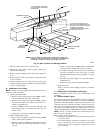
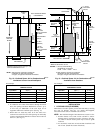
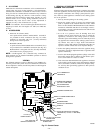
Fig. 20—Filter Installed for Side Inlet
A93045
FILTER
RETAINER
WASHABLE
FILTER
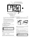
Fig. 21—Bottom Filter Arrangement
A96030
WASHABLE
FILTER
FILTER
SUPPORT
FILTER
RETAINER
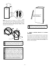
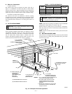
24
1
⁄2-IN. WIDE
CASINGS ONLY:
CUT AND FOLD
FACTORY-PROVIDED
FILTERS AS SHOWN
TO DESIRED SIZE.
17
1
⁄2-IN. WIDE
CASINGS ONLY:
INSTALL FIELD-SUPPLIED
FILTER FILLER STRIP
UNDER FILTER.
1″
24
1
/
2
″
3″
Fig. 22—Removing Bottom Closure Panel
A93047
BOTTOM
CLOSURE
PANEL
FRONT FILLER
PANEL
—18—