


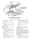
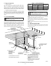
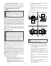
IV. INSTALLATION IN HORIZONTAL APPLICATIONS
These furnaces can be installed horizontally in either horizontal
left or right discharge position. In a crawlspace, furnace can either
be hung from floor joist or installed on suitable blocks or pad.
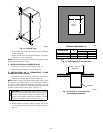
Furnace can be suspended from each corner by hanger bolts and
angle iron supports. (See Fig. 19.) Cut hanger bolts (4 each 3/8-in.
all-thread rod) to desired length. Use 1 X 3/8-in. flat washers,
3/8-in. lockwashers, and 3/8-in. nuts on hanger rods as shown in
Fig. 19. Dimples are provided for hole locations. (See Fig. 2.)
CAUTION: The entire length of furnace MUST be
supported when furnace is used in a horizontal position to
ensure proper draining.
V. AIR DUCTS
A. General Requirements
The duct system should be designed and sized according to
accepted national standards such as those published by: Air
Conditioning Contractors Association (ACCA), Sheet Metal and
Air Conditioning Contractors National Association (SMACNA) or
American Society of Heating, Refrigerating and Air Conditioning
Engineers (ASHRAE). Or consult factory The Air Systems Design
Guidelines reference tables available from your local distributor.
The duct system should be sized to handle the required system
design CFM at the design static pressure.
When a furnace is installed so that the supply ducts carry air to
areas outside the space containing the furnace, the return air must
also be handled by a duct(s) sealed to the furnace casing and
terminating outside the space containing the furnace.
Secure ductwork with proper fasteners for type of ductwork used.
Seal supply- and return-duct connections to furnace with code
approved tape or duct sealer.
Flexible connections should be used between ductwork and
furnace to prevent transmission of vibration. Ductwork passing
through unconditioned space should be insulated to enhance
system performance. When air conditioning is used, a vapor
barrier is recommended.
Maintain a 1-in. clearance from combustible materials to supply air
ductwork for a distance of 36 in. horizontally from the furnace. See
NFPA 90B or local code for further requirements.
B. Ductwork acoustical treatment
Metal duct systems that do not have a 90 degree elbow and 10 ft
of main duct to the first branch take-off may require internal
acoustical lining. As an alternative, fibrous ductwork may be used
if constructed and installed in accordance with the latest edition of
SMACNA construction standard on fibrous glass ducts. Both
acoustical lining and fibrous ductwork shall comply with NFPA
90B as tested by UL Standard 181 for Class 1 Rigid air ducts.
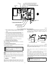
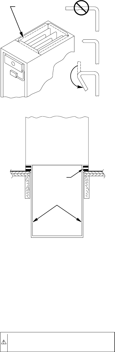
C. Supply Air Connections
UPFLOW FURNACES
Connect supply-air duct to 3/4-in. flange on furnace supply-air
outlet. The supply-air duct attachment must ONLY be connected
to furnace supply-/outlet-air duct flanges or air conditioning coil
casing (when used). DO NOT cut main furnace casing to attach
supply side air duct, humidifier, or other accessories. All accesso-
ries MUST be connected external to furnace main casing.
DOWNFLOW FURNACES
Connect supply-air duct to supply-air opening on furnace. The
supply-air duct attachment must ONLY be connected to furnace
supply/outlet or air conditioning coil casing (when used), when
installed on non-combustible material. When installed on combus-
tible material, supply-air duct attachment must ONLY be con-
nected to an accessory subbase or factory approved air condition-
ing coil casing. DO NOT cut main furnace casing to attach supply
side air duct, humidifier, or other accessories. All accessories
MUST be connected external to furnace main casing.
HORIZONTAL FURNACES
Connect supply-air duct to supply air opening on furnace. The
supply-air duct attachment must ONLY be connected to furnace
supply/outlet or air conditioning coil casing (when used). DO NOT
cut main furnace casing to attach supply side air duct, humidifier,
or other accessories. All accessories MUST be connected external
to furnace main casing.
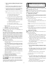
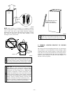
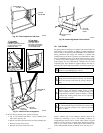
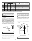
Fig. 17—Duct Flanges
A93029
NO
YES
YES
PERFORATED
DISCHARGE DUCT
FLANGE
210°
MIN
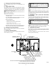
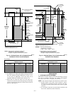
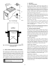
Fig. 18—Furnace, Plenum, and Subbase Installed on a
Combustible Floor
A78651
DOWNFLOW
SUBBASE
SHEET METAL
PLENUM
FURNACE
(OR COIL CASING
WHEN USED)
—16—