


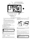
3. Route extended collector box pressure tube behind inducer
motor bracket then between inducer motor and pressure
switch.
4. Connect collector box pressure tube (green label) to pres-
sure switch connection labeled COLLECTOR BOX.
5. Use remaining smaller diameter tube (factory-supplied in
loose parts bag) to extend collector box pressure tube (pink
label) which was previously connected to pressure switch.
6. Route this extended tube (pink label) to condensate trap
relief port connection.
7. Determine appropriate length, cut, and connect tube.
8. Clamp tube to relief port connection.
E. Condensate Trap Freeze Protection
Refer to Condensate Drain Protection section for recommenda-
tions and procedures.
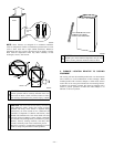
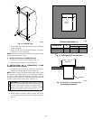
F. Construct a Working Platform
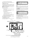
Construct working platform where all required furnace clearances
are met. (See Fig. 3 and 10.)
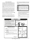
CAUTION: The condensate trap MUST be installed
below furnace. See Fig. 4 for dimensions. The drain
connection to condensate trap must also be properly
sloped to an open drain.
NOTE: Vent pipe length is restricted to a minimum of 5 ft. (See
Table 4.)
NOTE: A 12-in. minimum horizontal pipe section is recom-
mended with short (5 to 8 ft) vent systems. This recommendation
is to reduce excessive condensate droplets from exiting the vent
pipe. (See Fig. 10 or 33.)
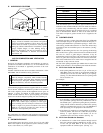
LOCATION
I. GENERAL
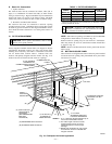
When a furnace is installed so that supply ducts carry air to areas
outside the space containing the furnace, return air must also be
handled by ducts sealed to furnace casing. The ducts terminate
outside the space containing the furnace to ensure there will not be
a negative pressure condition within equipment room or space.
This furnace must be installed so electrical components are
protected from water.
Locate furnace as close to center of air distribution system as
possible.
Locate furnace so vent pipe maximum length is not exceeded.
Refer to Table 4—Maximum Allowable Pipe Length.
Provide ample space for servicing and cleaning. Always comply
with minimum fire protection clearances shown on unit’s clear-
ance to combustibles label. (See Fig. 3.) Locate furnace where
available electric power and gas supplies meet specifications on
furnace rating plate.
CAUTION: Do not install furnace in a corrosive or
contaminated atmosphere. Make sure all combustion and
circulating air requirements are met.
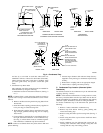
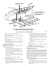
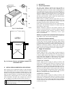
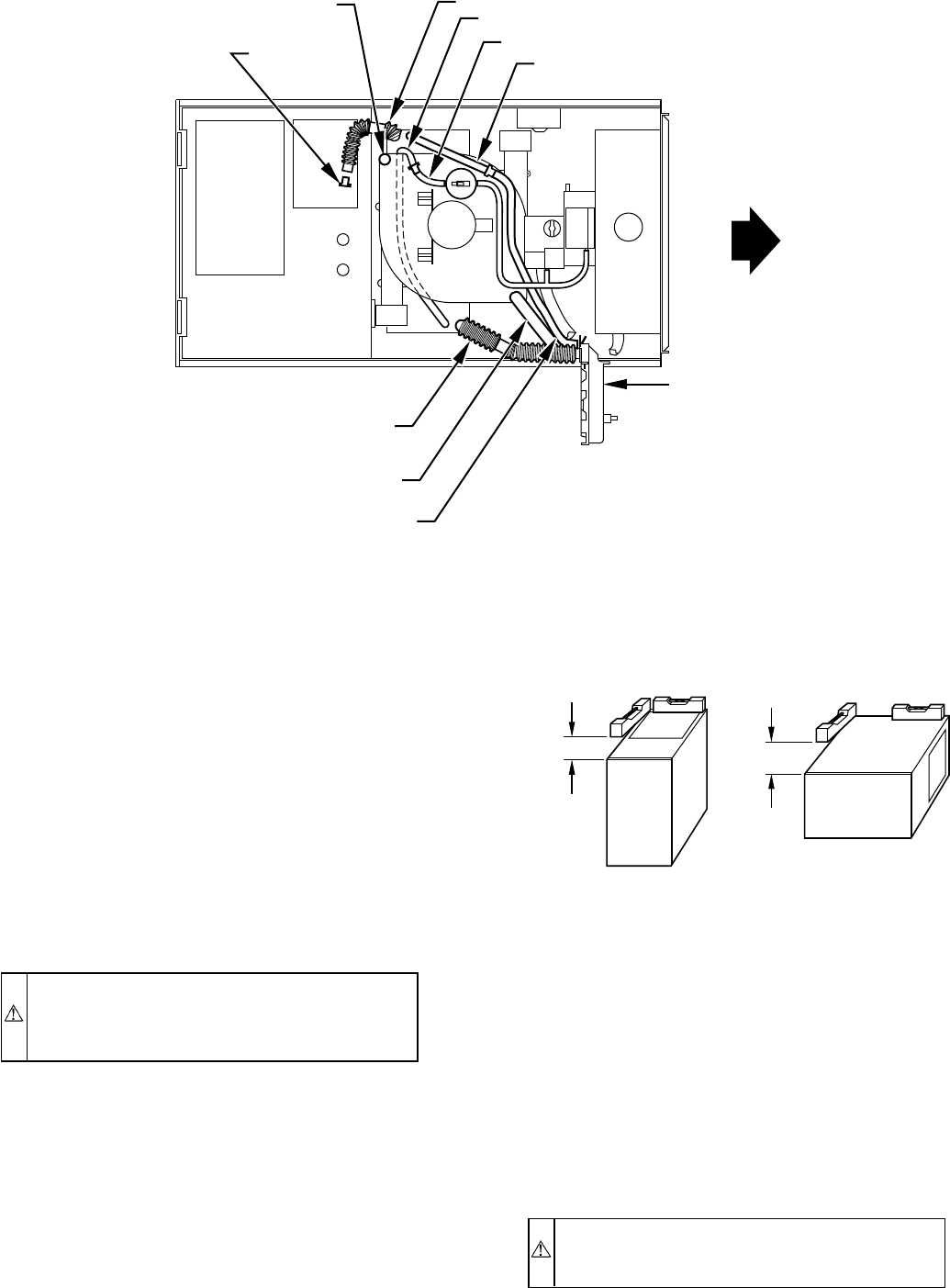
Fig. 11—Horizontal Right Tube Configuration
A93303
PLUG
COLLECTOR BOX DRAIN TUBE
(BLUE AND WHITE STRIPED)
INDUCER HOUSING
DRAIN TUBE (VIOLET)
COLLECTOR BOX
EXTENSION TUBE
COLLECTOR BOX TUBE (GREEN)
CAP
COLLECTOR BOX DRAIN TUBE (BLUE)
COLLECTOR BOX TUBE (PINK)
CONDENSATE
TRAP
COLLECTOR BOX EXTENSION TUBE
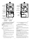
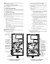
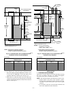
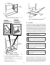
NOTE: For proper furnace operation, install furnace so that it is
level or pitched forward within 1/2 in. to ensure proper condensate
drainage from secondary heat exchangers.
A93025
UPFLOW OR DOWNFLOW HORIZONTAL
FRONT
LEVEL (0″)
TO
1
⁄2″ MAX
LEVEL (0″)
TO
1
⁄2″ MAX
FRONT
—11—