


CAUTION: Furnace control must be grounded for
proper operation or control will lock out. Control is
grounded through green wire routed to gas valve and
burner box screw.
I. 115-V WIRING
Before proceeding with electrical connections, make certain that
voltage, frequency, and phase correspond to that specified on unit
rating plate. Also, check to be sure that service provided by utility
is sufficient to handle load imposed by this equipment. Refer to
rating plate or Table 3 for equipment electrical specifications.
Make all electrical connections in accordance with National
Electrical Code (NEC) ANSI/NFPA 70-1999 and any local codes
or ordinances that might apply. For Canadian installations, all
electrical connections must be made in accordance with Canadian
Electrical Code CSA C22.1 or subauthorities having jurisdiction.
Use a separate, fused branch electrical circuit containing a properly
sized fuse or circuit breaker for this furnace. See Table 3 for wire
size and fuse specifications. A disconnecting means must be
located within sight from and readily accessible to furnace.
NOTE: Proper polarity must be maintained for 115-v wiring. If
polarity is incorrect, control center status code indicator light will
flash rapidly and furnace will NOT operate.
WARNING: The cabinet MUST have an uninterrupted
or unbroken ground according to NEC ANSI/NFPA
70-1999 and Canadian Electrical Code CSA C22.1 or
local codes to minimize personal injury if an electrical
fault should occur. This may consist of electrical wire or
conduit approved for electrical ground when installed in
accordance with existing electrical codes. Do not use gas
piping as an electrical ground. Failure to follow this
warning could result in electrical shock, fire, or death.
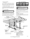
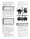
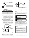
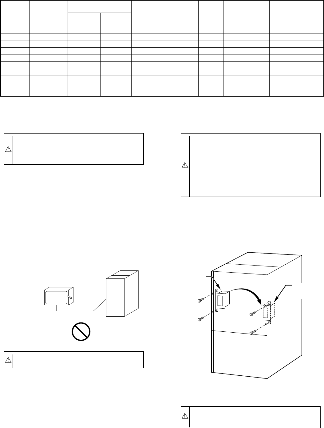
J-BOX RELOCATION
1. Remove 2 screws holding auxiliary J-box. (See Fig. 25.)
2. Rotate J-box 180° and attach box to right side, using holes
provided.
CAUTION: If manual disconnect switch is to be
mounted on furnace, select a location where a drill or
fastener will not contact electrical or gas components.
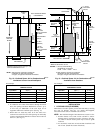
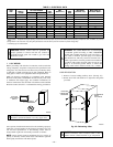
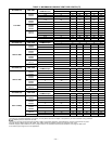
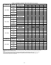
TABLE 3—ELECTRICAL DATA
UNIT
SIZE
VOLTS—
HERTZ—
PHASE
OPERATING
VOLTAGE RANGE
MAX
UNIT
AMPS
UNIT
AMPACITY†
MIN
WIRE
SIZE
MAX WIRE
LENGTH (FT)‡
MAX FUSE OR
CKT BKR AMPS**
Max* Min*
024040 115—60—1 127 104 6.1 8.4 14 44 15
036040 115—60—1 127 104 7.3 10.0 14 37 15
024060 115—60—1 127 104 6.1 8.4 14 44 15
036060 115—60—1 127 104 7.1 9.8 14 38 15
048060 115—60—1 127 104 9.5 12.8 14 29 15
036080 115—60—1 127 104 7.6 10.4 14 36 15
048080 115—60—1 127 104 10.0 13.4 14 28 15
060080 115—60—1 127 104 14.1 18.4 12 31 20
048100 115—60—1 127 104 10.2 13.5 14 27 15
060100 115—60—1 127 104 14.8 19.3 12 30 20
060120 115—60—1 127 104 14.6 19.1 12 30 20
* Permissible limits of voltage range at which unit will operate satisfactorily.
† Unit ampacity = 125 percent of largest operating component’s full load amps plus 100 percent of all other potential operating components’ (EAC, humidifier, etc.) full load
amps.
‡ Length shown is as measured 1 way along wire path between unit and service panel for maximum 2 percent voltage drop.
** Time-delay type is recommended.
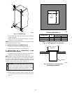
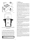
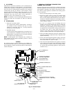
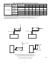
CAUTION: Do not connect aluminum wire between
disconnect switch and furnace. Use only copper wire.
A93033
COPPER
WIRE ONLY
ELECTRIC
DISCONNECT
SWITCH
ALUMINUM
WIRE
Fig. 25—Relocating J-Box
A93051
ALTERNATE
FIELD
LOCATION
FACTORY
INSTALLED
LOCATION
—20—