


SAFETY CONSIDERATIONS
Installing and servicing heating equipment can be hazardous due to
gas and electrical components. Only trained and qualified person-
nel should install, repair, or service heating equipment. Untrained
personnel can perform basic maintenance functions such as clean-
ing and replacing air filters. All other operations must be per-
formed by trained service personnel. When working on heating
equipment, observe precautions in literature, on tags, and on labels
attached to or shipped with unit and other safety precautions that
may apply.
Follow all safety codes, including the National Fuel Gas Code
(NFGC) NFPA 54/ANSI Z223.1-1996, and the Installation Stan-
dards, Warm Air Heating and Air Conditioning Systems (NFPA
90B) ANSI/NFPA 90B. In Canada, refer to the current edition of
the CAN/CGA-B149.1 and .2-M95 National Standard of Canada,
Natural Gas and Propane Installation Codes (NSCNGPIC). Wear
safety glasses and work gloves. Have a fire extinguisher available
during start-up and adjustment procedures and service calls.
Recognize safety information. This is the safety-alert symbol
.
When you see this symbol on the unit and in instructions or
manuals, be alert to the potential for personal injury.
Understand the signal words DANGER, WARNING, and CAU-
TION. These words are used with the safety-alert symbol. DAN-
GER identifies most serious hazards which will result in severe
personal injury or death. WARNING signifies hazards which
could result in personal injury or death. CAUTION is used to
identify unsafe practices which would result in minor personal
injury or product and property damage. NOTE is used to highlight
suggestions which will result in enhanced installation, reliability,
or operation.
ELECTROSTATIC DISCHARGE (ESD) PRECAUTIONS
CAUTION: Electrostatic discharge can affect electronic
components. Take precautions during furnace installation
and servicing to protect the furnace electronic control.
Precautions will prevent electrostatic discharges from
personnel and hand tools which are held during the
procedure. These precautions will help to avoid exposing
the control to electrostatic discharge by putting the
furnace, the control, and the person at the same electro-
static potential.
1. Disconnect all power to the furnace. DO NOT TOUCH
THE CONTROL OR ANY WIRE CONNECTED TO THE
CONTROL PRIOR TO DISCHARGING YOUR BODY’S
ELECTROSTATIC CHARGE TO GROUND.
2. Firmly touch a clean, unpainted, metal surface of the
furnace chassis which is close to the control. Tools held in
a person’s hand during grounding will be satisfactorily
discharged.
3. After touching the chassis you may proceed to service the
control or connecting wires as long as you do nothing that
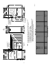
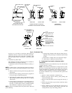
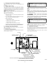
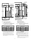
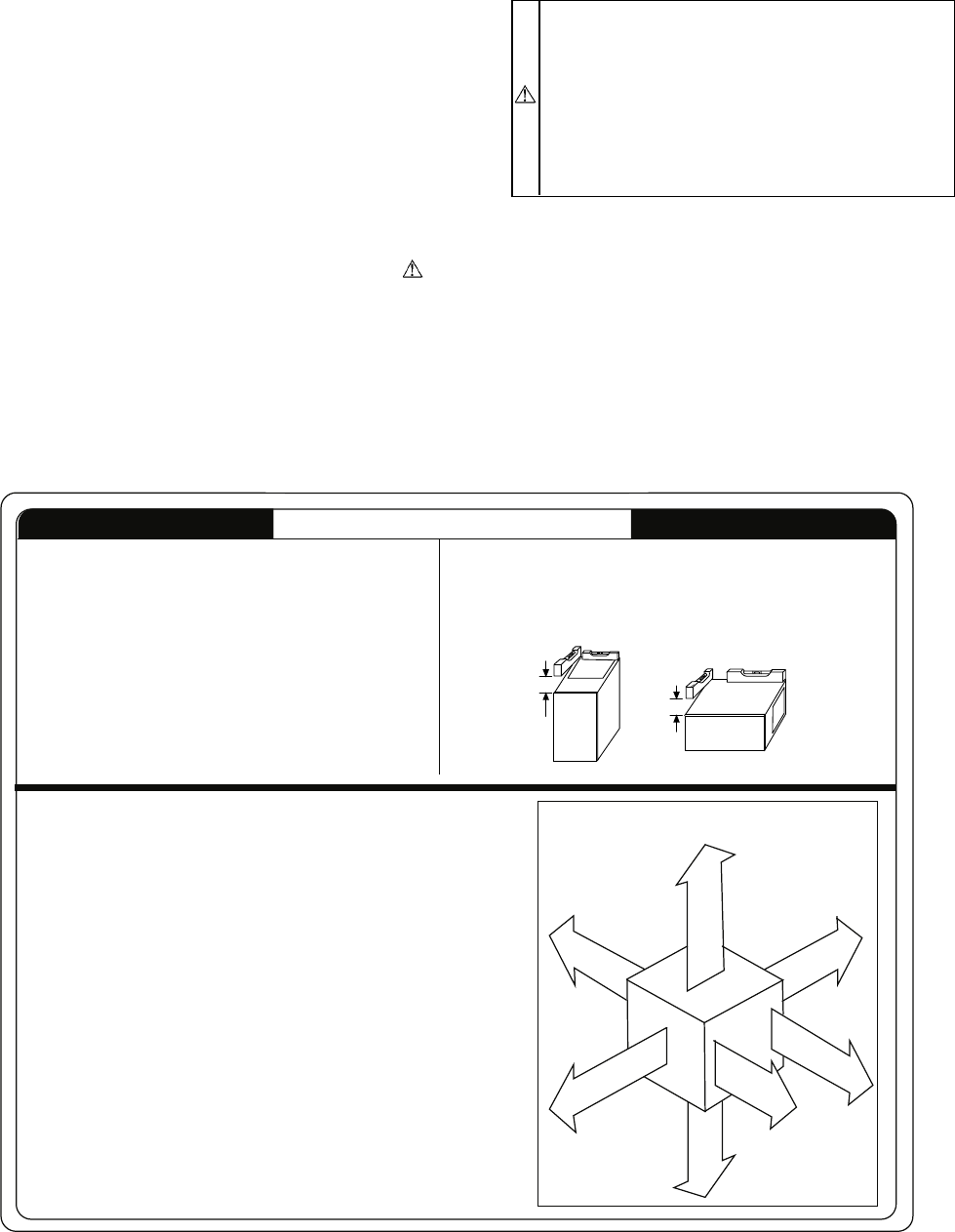
→ Fig. 3—Clearances to Combustibles
A99101
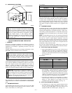
This forced air furnace is equipped for use with natural gas at altitudes 0 -
10,000 ft (0 - 3,050m), except 140 size Furnaces are only approved for
altitudes 0 - 7,000ft. (0 - 2,135m).
An accessory kit, supplied by the manufacturer, shall be used to convert to
propane gas use or may be required for some natural gas applications.
This furnace is for indoor installation in a building constructed on site. This
furnace may be installed in a manufactured (mobile) home when stated on
rating plate and using factory authorized kit.
This furnace may be installed on combustible flooring in alcove or closet at
minimum clearance from combustible material.
This appliance requires a special venting system. Refer to the installation
instructions for parts list and method of installation. This furnace is for use with
schedule-40 PVC, PVC-DWV, or ABS-DWV pipe, and must not be vented in
common with other gas-fired appliances. Construction through which vent/air
intake pipes may be installed is maximum 24 inches (600 mm), minimum 3/4
inches (19 mm) thickness (including roofing materials).
MINIMUM INCHES CLEARANCE TO
COMBUSTIBLE CONSTRUCTION
*
Minimum front clearance for service 30 inches (762mm).
140 size furnaces require 1 inch back clearance to combustible materials.
For installation on combustible floors only when installed on special base
No. KGASB0201ALL, Coil Assembly, Part No. CD5 or CK5, or Coil Casing,
Part No. KCAKC.
Clearance shown is for air inlet and air outlet end.
Line contact is permissible only between lines formed by intersections of
top and two sides of furnace jacket, and building joists, studs, or framing.
120 and 140 size Furnaces require 1 inch bottom clearance to combustible
materials.
Ø
§
Clearance in inches .
Vent clearance to
combustibles 0".
This furnace is approved for UPFLOW, DOWNFLOW and
HORIZONTAL installations.
*
BOTTOM
0"
Ø
3"
0"
§
0"
TOP/PLENUM
1"
0"
§
30
MIN
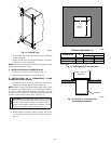
ALL POSITIONS:
DOWNFLOW POSITIONS:
HORIZONTAL POSITIONS:
S
I
D
E
F
R
O
N
T
B
C
K
A
S
E
R
V
I
E
C
F
R
O
N
T
S
I
D
E
U
F
R
N
A
C
E
Clearance arrows
do not change with
furnace orientation.
†
†
†
†
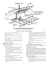
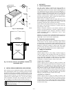
HORIZONTAL
UPFLOW OR
DOWNFLOW
1/2" MAX
FRONT
FRONT
1/2" MAX
TO
LEVEL (0")
LEVEL (0")
TO
†
†
INSTALLATION
Furnace must be installed level, or pitched forward within 1/2 inch of
level for proper drainage. Failure will result in equipment or property
damage. See Installation Manual for IMPORTANT unit support details
on horizontal applications.
324999-201 REV. A
(LIT. TOP)
FRONT
FRONT
—3—