


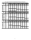
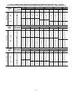
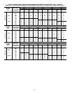
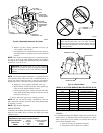

c. Measure time (in sec) for gas meter test dial to complete
1 revolution.
d. Refer to Table 9 for cu ft of gas per hr.
e. Multiply gas rate (cu ft/hr) X heating value (Btu/cu ft)
using natural gas heating value from local gas
utility/supplier.
EXAMPLE:
Btu heating input = Btu/cu ft X cu ft/hr
Heating value of gas = 975 Btu/cu ft
Time for 1 revolution of 2-cu ft dial = 70 sec
Gas rate = 103 cu ft/hr (from Table 9)
Btu heating input = 103 X 975 = 100,425 Btuh
In this example, the orifice size and manifold pressure
adjustment is within ±2 percent of the furnace input
rate.
B. Set Temperature Rise
CAUTION: Temperature rise must be within limits
specified on unit rating plate. Recommended operation is
at midpoint of rise or above. Failure to follow this caution
may result in condensing or overheating the heat ex-
changers.
Determine and adjust air temperature rise as follows:
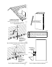
1. Place thermometers in return and supply ducts as close to
furnace as possible. Be sure thermometers do not see heat
exchanger so that radiant heat does not affect readings. This
practice is particularly important with straight-run ducts.
2. When thermometer readings stabilize, subtract return-air
temperature from supply-air temperature to determine air
temperature rise.
3. Adjust temperature rise by adjusting blower speed. Increase
blower speed to reduce temperature rise. Decrease blower
speed to increase temperature rise.
WARNING: Disconnect 115-v electrical power before
changing speed tap. Failure to follow this warning could
result in personal injury.
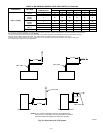
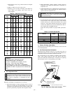
4. To change blower motor speed selections for heating mode,
remove blower motor lead from control center HEAT
terminal. (See Fig. 27.) Select desired blower motor speed
lead from 1 of the other terminals and relocate it to HEAT
terminal. See Table 10 for lead color identification. Recon-
nect original lead on SPARE terminal.
Follow this same procedure for proper COOL speed selec-
tion.
C. Blower Off Delay (Heat Mode)
The main blower off time delay period is factory-set at 135 sec and
is not field-adjustable.
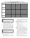
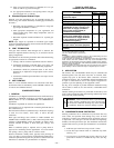
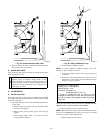
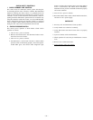
D. Set Thermostat Heat Anticipator
Thermostat heat anticipator must be set to match amp draw of
components in R-W circuit. Accurate amp draw measurements can
be obtained at thermostat subbase terminals R and W.
Fig. 42 illustrates an easy method of obtaining these measure-
ments. Amp reading should be taken after blower motor has
started. See thermostat manufacturer’s instructions for adjusting
heat anticipator and for varying heating cycle length.
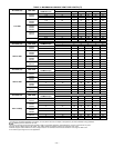
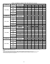
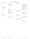
TABLE 9—GAS RATE (CU FT/HR)
SECONDS
FOR 1
REVOLUTION
SIZE OF TEST DIAL
SECONDS
FOR 1
REVOLUTION
SIZE OF TEST DIAL
1
cu ft
2
cu ft
5
cu ft
1
cu ft
2
cu ft
5
cu ft
10
11
12
13
14
360
327
300
277
257
720
655
600
555
514
1800
1636
1500
1385
1286
50
51
52
53
54
72
71
69
68
67
144
141
138
136
133
360
355
346
340
333
15
16
17
18
19
240
225
212
200
189
480
450
424
400
379
1200
1125
1059
1000
947
55
56
57
58
59
65
64
63
62
61
131
129
126
124
122
327
321
316
310
305
20
21
22
23
24
180
171
164
157
150
360
343
327
313
300
900
857
818
783
750
60
62
64
66
68
60
58
56
54
53
120
116
112
109
106
300
290
281
273
265
25
26
27
28
29
144
138
133
129
124
288
277
267
257
248
720
692
667
643
621
70
72
74
76
78
51
50
48
47
46
103
100
97
95
92
257
250
243
237
231
30
31
32
33
34
120
116
113
109
106
240
232
225
218
212
600
581
563
545
529
80
82
84
86
88
45
44
43
42
41
90
88
86
84
82
225
220
214
209
205
35
36
37
38
39
103
100
97
95
92
206
200
195
189
185
514
500
486
474
462
90
92
94
96
98
40
39
38
38
37
80
78
76
75
74
200
196
192
188
184
40
41
42
43
44
90
88
86
84
82
180
176
172
167
164
450
439
429
419
409
100
102
104
106
108
36
35
35
34
33
72
71
69
68
67
180
178
173
170
167
45
46
47
48
49
80
78
76
75
73
160
157
153
150
147
400
391
383
375
367
110
112
116
120
33
32
31
30
65
64
62
60
164
161
155
150
TABLE 10–SPEED SELECTOR
COLOR SPEED
FACTORY-
SHIPPED
CONNECTION
Black High Cool
Yellow (When Present) Medium High Spare
Blue Medium Low Heat
Red Low Spare
White Common Com
Fig. 42—Amp Draw Check with Ammeter
A80201
R Y W G
10 TURNS
THERMOSTAT SUBBASE
TERMINALS WITH
THERMOSTAT REMOVED
HOOK-AROUND
VOLT/AMMETER
EXAMPLE:
5.0 AMPS ON AMMETER
10 TURNS AROUND JAWS
= 0.5 AMPS FOR THERMOSTAT SETTING
FROM UNIT 24-VOLT
TERMINAL BLOCK
—38—