


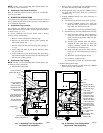
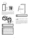
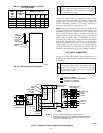
3. Install another nut on other side of furnace base. (Install flat
washer if desired.)
4. Adjust outside nut to provide desired height, and tighten
inside nut to secure arrangement.
NOTE: Bottom closure must be used when leveling legs are used.
See Bottom Closure Panel section.
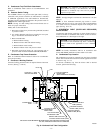
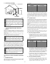
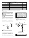
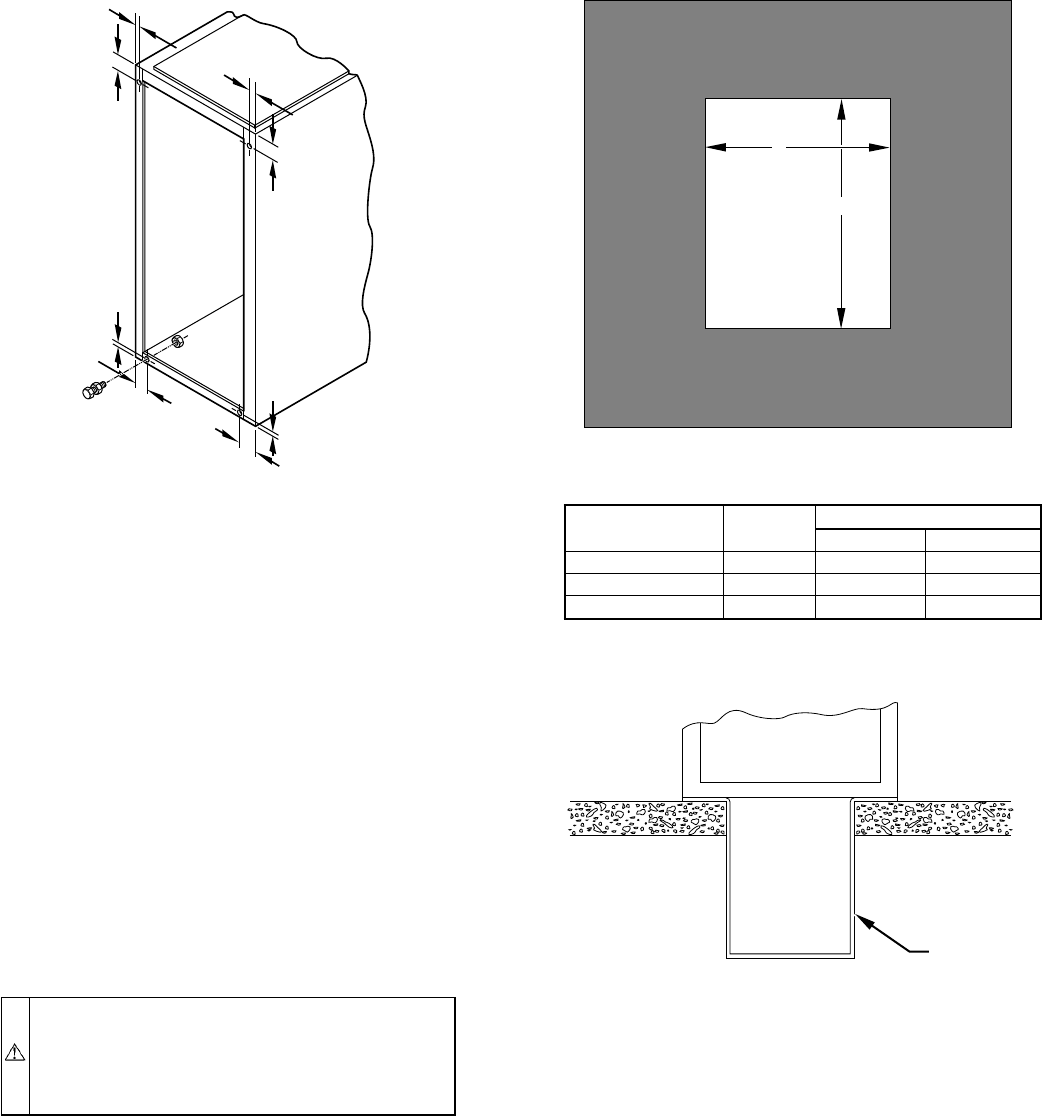
II. INSTALLATION ON A CONCRETE SLAB
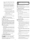
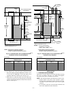
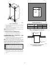
1. Construct hole in floor per dimensions in Fig. 15.
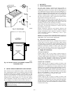
2. Place plenum and furnace as shown in Fig. 16.
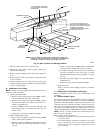
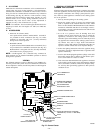
III. INSTALLATION ON A COMBUSTIBLE FLOOR
(DOWNFLOW APPLICATIONS)
1. Cut and frame hole in floor per dimensions in Installation
Instructions packaged with downflow subbase kit.
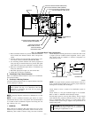
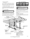
NOTE: Remove furnace perforated, discharge duct flanges when
they interfere with mating flanges on coil on downflow subbase.
To remove furnace perforated, discharge duct flange, use wide
duct pliers or duct flange tool to bend flange back-and-forth until
it breaks off. Be careful of sharp edges. (See Fig. 17.)
WARNING: Do not bend duct flanges inward as shown
in Fig. 17. This will affect airflow across heat exchangers
and may cause limited cycling or premature heat ex-
changer failure. Remove duct flange completely or bend
it inward a minimum of 210° as shown in Fig. 17.
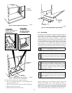
2. When complete, downflow subbase, plenum, and furnace
(or coil casing when used) should be installed as shown in
Fig. 18.
Fig. 14—Leveling Legs
A89014
1
3
⁄4″
1
3
⁄4″
1
3
⁄4″
1
3
⁄4″
5
⁄16″
5
⁄16″
5
⁄16″
5
⁄16″
Fig. 15—Floor Opening in Concrete Slab
OPENING DIMENSIONS (IN.)
FURNACE
CASING WIDTH
A
B
Heat Only Heat/Cool*
17-1/2 16-7/16 19-5/8 19-7/16
21 19-7/8 19-5/8 19-7/16
24-1/2 23-7/16 19-5/8 19-7/16
* These dimensions apply when a model CD or CK Evaporator Coil casing is
to be installed.
A73382
HOLE IN
FLOOR
A
B
Fig. 16—Furnace on a Concrete Slab
(Non-Garage Installation)
A73383
FURNACE
PLENUM
—15—